View All

Please refer to the English Version as our Official Version.Return

Europe
France(Français) Germany(Deutsch) Italy(Italia) Russian(русский) Poland(polski) Czech(Čeština) Luxembourg(Lëtzebuergesch) Netherlands(Nederland) Iceland(íslenska) Hungarian(Magyarország) Spain(español) Portugal(Português) Turkey(Türk dili) Bulgaria(Български език) Ukraine(Україна) Greece(Ελλάδα) Israel(עִבְרִית) Sweden(Svenska) Finland(Svenska) Finland(Suomi) Romania(românesc) Moldova(românesc) Slovakia(Slovenská) Denmark(Dansk) Slovenia(Slovenija) Slovenia(Hrvatska) Croatia(Hrvatska) Serbia(Hrvatska) Montenegro(Hrvatska) Bosnia and Herzegovina(Hrvatska) Lithuania(lietuvių) Spain(Português) Switzerland(Deutsch) United Kingdom(English)
Asia/Pacific
Japan(日本語) Korea(한국의) Thailand(ภาษาไทย) Malaysia(Melayu) Singapore(Melayu) Vietnam(Tiếng Việt) Philippines(Pilipino)
Africa, India and Middle East
United Arab Emirates(العربية) Iran(فارسی) Tajikistan(فارسی) India(हिंदी) Madagascar(malaɡasʲ)
South America / Oceania
New Zealand(Maori) Brazil(Português) Angola(Português) Mozambique(Português)
North America
United States(English) Canada(English) Haiti(Ayiti) Mexico(español)
HomeProductsIntegrated Circuits (ICs)Interface - Drivers, Receivers, TransceiversLTC487CSW#TRPBF
LTC487CSW#TRPBF Image
Image may be representation.
See specifications for product details.
EXPRESS OPTION
Payment method

LTC487CSW#TRPBF - Analog Devices Inc.

Manufacturer Part Number
LTC487CSW#TRPBF
Manufacturer
Analog Devices, Inc.
Allelco Part Number
32D-LTC487CSW#TRPBF
Warranty
1 Year Allelco Warranty - Find out more
Stock Status:
5,052 pcs available, New & Original
Parts Description
IC DRIVER 4/0 16SOIC
Package
16-SO
Data sheet
LTC487CSW#TRPBF.pdf

Environmental Information

Material Declaration LTC487CSW#TRPBF.pdf

PCN Design/Specification

Cylindrical Battery Holders.pdf

Other Related Documents

Tape and Reel Packaging.pdf
RoHs Status
ROHS3 Compliant
Our certification
In stock: 5052
  • Unit Price: $5.716
  • Subtotal: $0.00

Want a better price?
Add to Cart and Submit RFQ now, we'll contact you immediately.

Quantity Unit Price Ext. Price
1+ $5.716 $5.72
200+ $2.213 $442.60
500+ $2.134 $1,067.00
1000+ $2.096 $2,096.00
The above prices does not include taxes and freight rates, which will be calculated on the order pages.

Specifications

LTC487CSW#TRPBF Tech Specifications
Analog Devices Inc. - LTC487CSW#TRPBF technical specifications, attributes, parameters and parts with similar specifications to Analog Devices Inc. - LTC487CSW#TRPBF

Product Attribute Attribute Value
Manufacturer Analog Devices, Inc.
Voltage - Supply 4.75V ~ 5.25V
Type Driver
Supplier Device Package 16-SO
Series -
Protocol RS422, RS485
Package / Case 16-SOIC (0.295', 7.50mm Width)
Product Attribute Attribute Value
Package Tape & Reel (TR)
Operating Temperature 0°C ~ 70°C
Number of Drivers/Receivers 4/0
Mounting Type Surface Mount
Duplex -
Data Rate -
Base Product Number LTC487

Environmental & Export Classifications

ATTRIBUTE DESCRIPTION
RoHs Status ROHS3 Compliant
Moisture Sensitivity Level (MSL) 1 (Unlimited)
REACH Status REACH Unaffected
ECCN EAR99
HTSUS 8542.39.0001

Parts Introduction

LTC487CSW#TRPBF Image
LTC487CSW#TRPBF (1)

Manufacturer Part Number

LTC487CSW#TRPBF

Manufacturer

Analog Devices, Inc.

Introduction

The LTC487 is a high-speed, quad differential line driver designed for RS-422 and RS-485 applications.

Product Features and Performance

Quad differential line driver

High-speed operation up to 10Mbps

Supports RS-422 and RS-485 protocols

Adjustable slew rate control

Short-circuit and thermal protection

Low supply current of 10mA

Product Advantages

High-speed operation for fast data transmission

Quad design for multi-channel applications

Adjustable slew rate for customized performance

Protection features for reliable operation

Key Technical Parameters

Operating voltage: 4.75V to 5.25V

Number of drivers/receivers: 4/0

Protocols supported: RS-422, RS-485

Driver type: Quad differential line driver

Operating temperature: 0°C to 70°C

Quality and Safety Features

RoHS3 compliant

Short-circuit and thermal protection

Compatibility

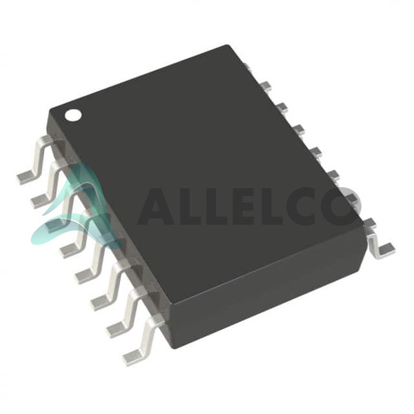
Surface mount package: 16-SOIC (0.295", 7.50mm width)

Tape and reel packaging

Application Areas

Industrial control systems

Telecommunications equipment

Instrumentation and test equipment

Computer peripherals

RS-422 and RS-485 bus systems

Product Lifecycle

This product is currently in production and not nearing discontinuation.

Replacement or upgrade options are available from Analog Devices.

Key Reasons to Choose This Product

High-speed operation up to 10Mbps for fast data transmission

Quad design for multi-channel applications

Adjustable slew rate for customized performance

Protection features like short-circuit and thermal protection for reliable operation

RoHS3 compliance for environmental sustainability

Frequently Asked Questions(FAQ)

How does the LTC487CSW#TRPBF perform in terms of noise immunity when operating at its maximum specified data rate, and what design considerations are necessary for reliable communication in electrically noisy industrial environments?
The LTC487CSW#TRPBF is a full-duplex RS422/RS485 transceiver designed to meet stringent noise performance requirements inherent to the RS485 standard. It achieves robust differential signaling with a typical common-mode voltage range of -7V to +12V, enabling effective rejection of ground potential differences and external interference in industrial settings. When driven at higher data rates, proper termination of transmission lines becomes critical to prevent reflections that degrade signal integrity. Engineers should ensure impedance matching at both ends of the bus using 120-ohm resistors, especially in long cable runs or high-speed applications. Additionally, layout practices such as minimizing stubs, avoiding parallel routing near noise sources, and grounding the shield at one point reduce EMI susceptibility. While the device supports data rates up to 20 Mbps under ideal conditions, real-world performance depends heavily on PCB trace length and environmental factors. Therefore, system-level validation under actual operating conditions is recommended.
What are the key differences between the LTC487CSW#TRPBF and alternative components like the MAX3042BCWE+ when used in multi-drop RS485 networks, particularly regarding driver enable behavior and power consumption?
The LTC487CSW#TRPBF integrates four independent transmitters with no receivers, making it suitable for point-to-point or multi-drop configurations requiring multiple transmit paths. In contrast, the MAX3042BCWE+ is a quad receiver-only device, meaning it cannot drive the bus without an external transmitter. This makes the LTC487 more appropriate for systems needing bidirectional or multiple sender support. Regarding enable logic, the LTC487 features active-high driver enables, which simplifies integration with microcontrollers that use high-impedance outputs during reset. The MAX3042 lacks transmit functionality, so any comparison must involve pairing it with a separate driver IC. Power consumption differs significantly: the LTC487 draws approximately 2.5 mA per channel in operation, while the MAX3042 consumes around 0.5 mA per channel as a receiver. Thus, total system power varies based on configuration, but the LTC487 offers greater flexibility at the cost of higher current draw when transmitting.
Can the LTC487CSW#TRPBF be safely used in hot-plug applications, and what precautions must be taken to avoid latch-up or damage during insertion into a powered backplane?
The LTC487CSW#TRPBF is not specifically rated for hot-plugging per se, but its protection features—such as ±15 kV HBM ESD tolerance and robust input thresholds—provide some resilience. However, hot insertion can induce large voltage transients on VCC and I/O pins due to parasitic inductance and capacitance. To mitigate risk, designers should include series resistors (typically 22–100 Ω) on each line close to the connector to limit di/dt and suppress ringing. Ferrite beads on the supply rail further dampen surges. Additionally, a soft-start circuit or bulk decoupling capacitance helps stabilize VCC during insertion. Although the device complies with IEC 61000-4-2 Level 4, relying solely on internal protection is insufficient for repeated hot-plug cycles. For mission-critical systems, consider using dedicated hot-swap controllers or opting for devices explicitly qualified for live insertion.
What is the impact of supply voltage variation within the 4.75V to 5.25V range on the output swing and threshold levels of the LTC487CSW#TRPBF, and how does this affect interoperability with other RS485 transceivers?
The LTC487CSW#TRPBF operates from a tightly regulated 5V supply (±5%), resulting in consistent differential output voltages typically exceeding 1.5V even at minimum supply (4.75V). At 4.75V, the A–B differential swing remains above the RS485 specification minimum of 1.5V, ensuring compatibility with most receivers. Input thresholds scale proportionally with supply: the receiver’s minimum differential input voltage (typically 200 mV) and common-mode range (-7V to +12V) remain stable across the supply window. This predictable behavior enhances interoperability with third-party transceivers that may operate at slightly different supplies. Nevertheless, marginal cases exist where very low-supply devices might exhibit reduced noise margins; thus, maintaining consistent node voltages across the network improves robustness. Designers should avoid cascading nodes with wide supply variations without level-shifting circuitry.
How does the LTC487CSW#TRPBF handle bus contention when multiple drivers attempt to assert opposite logic states simultaneously, and what mechanisms prevent damage or data corruption?
The LTC487CSW#TRPBF includes internal slew-rate control and failsafe biasing features that help manage bus contention scenarios. When multiple drivers are enabled simultaneously, the differential output voltage may momentarily fall outside valid logic levels, potentially causing indeterminate states on receiving nodes. However, the device’s high input impedance and differential receiver thresholds (>±120 mV) ensure that only sufficiently strong signals register as valid logic states. More importantly, the LTC487 implements automatic fail-safe biasing through internal pull-up and pull-down resistors on the A and B lines when all drivers are disabled. These resistors bias the idle bus toward a known state (typically A > B), preventing erroneous wake-ups due to floating inputs. During active contention, the slew-rate-limited rise/fall times minimize overshoot and ringing, reducing stress on the semiconductor junctions. Still, best practice dictates disabling unused drivers via enable pins to eliminate contention risks entirely.
Is it possible to cascade multiple LTC487CSW#TRPBF devices on a single RS485 bus without violating timing constraints or introducing excessive loading, and what are the practical limits for such topologies?
Cascading multiple LTC487CSW#TRPBF devices on a single RS485 bus is feasible provided certain guidelines are followed. Each LTC487 contributes two differential outputs (A and B), so a four-channel version effectively adds four transmitter pairs to the bus. Standard RS485 allows up to 32 unit loads, where one unit load equals 1/8 of a standard 12 kΩ termination resistor (~1.5 kΩ). The LTC487 presents less than 1/10th unit load (typically <1.2 kΩ), allowing dozens of devices before reaching the 32-unit-load limit. However, cumulative propagation delay increases with each additional node, potentially limiting maximum data rates in long buses. For instance, at 1 Mbps, skew between edges from multiple drivers could exceed the bit period if traces are unbalanced. Termination remains essential—place 120 Ω resistors at both ends and possibly mid-bus if stub lengths exceed λ/10 at the highest frequency. Signal attenuation over distance also imposes practical limits; beyond ~1,200 meters at 100 kbps, repeaters or buffers become necessary.
How does temperature drift affect the offset voltage and gain accuracy of the LTC487CSW#TRPBF in precision measurement applications, and what compensation strategies are advisable?
The LTC487CSW#TRPBF is primarily optimized for digital communication rather than analog signal conditioning, so its internal amplifiers are not calibrated for precision voltage translation. Offset voltage drift with temperature is unspecified in the datasheet but inferred to be on the order of several millivolts per degree Celsius based on similar parts. This makes the device unsuitable for direct analog sensor interfacing where absolute accuracy matters. Instead, it excels in converting digital data streams with minimal jitter and distortion. If analog conditioning is required upstream or downstream, use precision op-amps with <10 µV/°C drift alongside the LTC487. Alternatively, implement software calibration routines that measure baseline offsets during initialization and apply correction factors in firmware. Avoid relying on the LTC487’s internal comparators or amplifiers for critical thresholds unless redundancy and environmental testing confirm adequate margin.
What role does the Moisture Sensitivity Level (MSL) rating play in the handling and reflow profile selection for the LTC487CSW#TRPBF, and how should assembly houses treat this component during manufacturing?
The LTC487CSW#TRPBF has an MSL rating of 1, indicating it is not prone to moisture-induced defects and can withstand unlimited exposure time before baking. This simplifies storage and handling compared to higher-MSL devices. Assembly facilities can process tape-and-reel shipments immediately upon opening without pre-bake procedures. During reflow soldering, follow standard lead-free profiles: peak temperature between 235°C and 245°C for 30–60 seconds within the liquidus phase. Ensure conveyor speed and oven zones maintain thermal uniformity to avoid localized overheating. Since the package is plastic SOIC, avoid prolonged dwell above 260°C to prevent delamination. Post-assembly, conformal coating is acceptable but must allow rework access if needed. Compliance with IPC-J-STD-033 and J-STD-020 ensures safe processing, and no special packaging is required beyond standard dry storage.
How does the LTC487CSW#TRPBF compare to newer generations of RS485 transceivers like the LT8705 or ADM3489 in terms of power efficiency, feature set, and suitability for battery-powered embedded systems?
The LTC487CSW#TRPBF predates modern low-power designs and consumes around 10 mA total when active, which may be prohibitive for energy-constrained applications. Newer devices like the LT8705 integrate DC-DC converters and support sleep modes drawing sub-milliampere currents, offering superior power efficiency. The ADM3489 extends this with automatic shutdown and ultra-low quiescent current (<1 µA). In contrast, the LTC487 lacks any power-down capability and requires constant biasing. Functionally, the LTC487 provides basic 4-transmitter support without integrated protection or diagnostics. Modern alternatives often include hot-swap protection, fault detection, and configurable slew rates—features absent in the original LTC487. For retrofitting existing designs, the LTC487 remains viable in non-portable, always-on systems where size and proven reliability outweigh power concerns. However, new developments favor the newer parts for IoT, portable instrumentation, and distributed sensing networks.
Are there any known substitutional options for the LTC487CSW#TRPBF that offer improved EMC performance or extended industrial temperature ranges, and how do they compare in pin compatibility?
Substitutes listed include the MAX3042BCWE+, SP487CT-L/TR, and SP487CT-L, but these vary significantly in function and compatibility. The MAX3042 is receiver-only, making it incompatible without adding a separate driver. The SP487 variants (from Exar/Sipex) resemble the LTC487 in being 4-transmitter devices but typically support wider temperature ranges (-40°C to +85°C) and may include enhanced ESD protection. Pinout alignment is generally maintained across the LTC family, so drop-in replacement is possible if the broader specs meet requirements. However, verify enable logic polarity, supply voltage tolerance, and package dimensions (SOIC vs. TSSOP). For industrial environments demanding extended temps and stricter compliance, consider the MAX3485 or SN65HVD12, though they differ in pin count and functionality. Always validate timing diagrams and electrical characteristics under target operating conditions before substituting.

Parts with Similar Specifications

The three parts on the right have similar specifications to Analog Devices Inc. LTC487CSW#TRPBF

Product Attribute LTC487ISW#TRPBF LTC486ISW#TRPBF LTC487CSW#PBF LTC487ISW#PBF
Part Number LTC487ISW#TRPBF LTC486ISW#TRPBF LTC487CSW#PBF LTC487ISW#PBF
Manufacturer Analog Devices Inc. Analog Devices Inc. Analog Devices Inc. Analog Devices Inc.
Base Product Number - DAC34H84 MAX500 ADS62P42
Series - - - -
Data Rate - - - -
Number of Drivers/Receivers - - - -
Mounting Type - Surface Mount Through Hole Surface Mount
Supplier Device Package - 196-NFBGA (12x12) 16-PDIP 64-VQFN (9x9)
Duplex - - - -
Package / Case - 196-LFBGA 16-DIP (0.300', 7.62mm) 64-VFQFN Exposed Pad
Package - Tape & Reel (TR) Tube Tape & Reel (TR)
Voltage - Supply - - - -
Protocol - - - -
Operating Temperature - -40°C ~ 85°C 0°C ~ 70°C -40°C ~ 85°C
Type - - - -

LTC487CSW#TRPBF Datasheet PDF

Download LTC487CSW#TRPBF pdf datasheets and Analog Devices Inc. documentation for LTC487CSW#TRPBF - Analog Devices Inc..

Datasheets
Cylindrical Battery Holders.pdf
Environmental Information
Material Declaration LTC487CSW#TRPBF.pdf
PCN Design/Specification
Cylindrical Battery Holders.pdf
Other Related Documents
Tape and Reel Packaging.pdf

Customer Reviews

Evaluation: 10 Articles

  • Nath***rooks
    Jun 11, 2026

    Installed this power component in a converter board. Output remained stable under different load conditions and thermal performance was better than expected.

  • Dani***alkerTech
    Jun 1, 2026

    Product works, but setup took more effort than expected. Once configured the MCU ran reliably, although documentation support felt older compared with newer platforms. Fine for maintenance projects.

  • Yuki***aka88
    May 26, 2026

    信号通信プロジェクトでこのRS-485トランシーバーを使用しました。設置は簡単で、長距離ケーブルでも通信は安定していました。消費電力も、以前使用していたものより低くなっています。

  • Stev***aker
    May 20, 2026

    Solid diode for power rectification. Works well in switching circuits.

  • Bran***Lewis
    May 11, 2026

    Compact FPGA with good performance. Suitable for basic signal processing tasks.

  • Oliv***arris
    May 7, 2026

    Reliable I/O expander. Works well in embedded control applications.

  • Jess***Jones
    Apr 17, 2026

    It offers good value for the price, and the specifications match the description. I’ve been using it for two days with no issues, and I’ll definitely buy it again if I need it in the future.

  • Mich***Smith
    Apr 17, 2026

    Shipping was on time, the component pins are neatly aligned, and I tested 10 of them with a multimeter—all readings were within the specified range. Highly recommended.

  • Aman***arris
    Apr 3, 2026

    It was great—the entire process, from placing the order to receiving the package, went very smoothly. The components were consistent, the price was fair, and I had a very pleasant shopping experience.

  • Mike***nch
    Apr 3, 2026

    Better than expected! The resistance and capacitance readings were spot-on, and it passed the test on the first try. The service was reliable, and the packaging was thoughtful—I highly recommend it.

Write a Review

Your Email address will not be published.

Shipment

Delivery Time

In-stock items can be shipped within 24 hours. Some parts will be arranged for delivery within 1-2 days from the date all items arrive at our warehouse. And Allelco ships order once a day at about 17:00, except Sunday. Once the goods are shipped, the estimated delivery time depends on the shipping methods and Delivery destination. The table below shows are the logistic time for some common countries.

Delivery Cost

  1. Use your express account for shipment if you have one.
  2. Use our account for the shipment. Refer to the table below for the approximate charges.
(Different time frame / countries / package size has different price.)

Delivery Method

  1. Global Common Shipment by DHL / UPS / FedEx / TNT / EMS / SF we support.
  2. Others more shipping ways, please get in touch with your customer manager.

Common Countries Logistic Time Reference
Region Country Logistic Time(Day)
America United States 5
Brazil 7
Europe Germany 5
United Kingdom 4
Italy 5
Oceania Australia 6
New Zealand 5
Asia India 4
Japan 4
Middle East Israel 6
DHL & FedEx Shipment Charges Reference
Shipment charges(KG) Reference DHL(USD$)
0.00kg-1.00kg USD$30.00 - USD$60.00
1.00kg-2.00kg USD$40.00 - USD$80.00
2.00kg-3.00kg USD$50.00 - USD$100.00
Note:
The above table is for reference only. There may have some data bias for the uncontrollable factors.
Contact us if you have any questions.
  • QC (Quality Warranty)
  • Payment Support
  • Packaging
  • Certifications & Memberships

QC (Quality Warranty)

Allelco is committed to exceeding customer expectations through customer service excellence, order accuracy, and on-time delivery.
This is achieved through our commitment to the continual improvement of our processes, services, and products.


Strict quality inspection builds a solid foundation for electronic component quality.
  1. Visual inspection
  2. Performance testing and reliability verification
  3. Standardized full-process testing
  4. Precise control of every parameter
We eliminate defective components and ensure the stable operation of electronic devices through professional quality standards.

Payment Support

The payment method can be chosen from the methods shown below: Wire Transfer (T/T, Bank Transfer), Western Union, Credit card, PayPal.
  • HKBea
  • Paypal
  • MasterCard
  • Western-Union
  • VISA
Stable Delivery, Sincere Partnership — Your Faithful Supply Chain Partner
  • Efficient Supply Management
  • Cost-Saving Procurement
  • Fast Sourcing & Delivery
Contact us if you have any questions.

Packaging

Electrostatic Discharge Protection and Handling

All electrostatic-sensitive components are handled in accordance with electrostatic discharge control procedures. The products are hermetically sealed in anti-static safe packaging to prevent electrostatic damage. Appropriate labeling is also applied for identification and traceability. This ensures product integrity during storage, handling and transportation.


ESD

Certifications & Memberships

Third-party certified, strict quality control. Our certification
  • ISO 9001: 2015
  • ISO 13485: 2016
  • ISO 14001: 2015
  • ISO 28000: 2007
  • ISO 45001: 2018
  • GB/T 27922-2011
  • SMTA
  • IPC
  • ESD
  • PSMA
LTC487CSW#TRPBF Image

LTC487CSW#TRPBF

Analog Devices Inc.
32D-LTC487CSW#TRPBF

Want a better price? Add to Cart and Submit RFQ now, we'll contact you immediately.

0 RFQ
Shopping cart (0 Items)
It is empty.
Compare List (0 Items)
It is empty.
Feedback

Your feedback matters! At Allelco, we value the user experience and strive to improve it constantly.
Please share your comments with us via our feedback form, and we'll respond promptly.
Thank you for choosing Allelco.

Subject
E-mail
Comments
Captcha
Drag or click to upload file
Upload File
types: .xls, .xlsx, .doc, .docx, .jpg, .png and .pdf.
Max file size: 10MB