
Manufacturer Part Number
TLE9850QXXUMA1
Manufacturer
infineon-technologies
Introduction
The TLE9850QXXUMA1 is a high-performance, multi-functional, and scalable 32-bit ARM Cortex-M0 based microcontroller from Infineon's AURIX™ family. It offers a wide range of advanced features and peripherals, making it an ideal choice for a variety of embedded applications requiring high reliability, safety, and flexibility.
Product Features and Performance
ARM® Cortex®-M0 32-bit single-core processor running at 40MHz
Extensive peripheral set including LINbus, SSC, UART/USART, brown-out detection/reset, POR, PWM, and WDT
48KB FLASH program memory, 4KB EEPROM, and 4KB RAM
9x8-bit and 12x10-bit ADCs
External and internal oscillator options
Wide operating voltage range of 5.5V to 28V
Extended operating temperature range of -40°C to 150°C (TJ)
Surface mount 48-VFQFN Exposed Pad package
Product Advantages
Powerful 32-bit ARM Cortex-M0 core for efficient code execution
Comprehensive peripheral set for diverse application needs
Robust safety and reliability features for critical systems
Wide operating voltage and temperature range for flexible design
Small form factor package for space-constrained applications
Key Reasons to Choose This Product
Excellent performance and scalability for a wide range of embedded applications
Robust safety and reliability features for mission-critical systems
Flexible configuration and peripheral options for customized solutions
Proven track record of Infineon's AURIX™ microcontroller family
Cost-effective and readily available in tape and reel packaging
Quality and Safety Features
Robust brown-out detection and power-on reset for reliable operation
Integrated watchdog timer for system monitoring and fault tolerance
Extended temperature range for use in harsh environments
Rigorous quality control and testing processes
Compatibility
The TLE9850QXXUMA1 is compatible with other AURIX™ series microcontrollers, allowing easy migration and scalability for different application requirements.
Application Areas
Industrial automation and control systems
Automotive electronics and power steering
Home appliances and consumer electronics
Building automation and smart home devices
Medical equipment and healthcare applications
Product Lifecycle
The TLE9850QXXUMA1 is an active product in Infineon's AURIX™ microcontroller lineup. There are several equivalent or alternative models available, including the TLE9850QXX, TLE9851QXX, and TLE9852QXX series. For the most up-to-date information on product availability and alternative options, please contact our website's sales team.
 TLE9852QXXUMA1Infineon TechnologiesIC MCU 32BIT 48KB FLASH 48VQFN
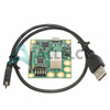 TLE98442QXAPPKITTOBO1Infineon TechnologiesTLE9844-2QX_APPKIT
 TLE9855QXXUMA1Infineon TechnologiesIC MCU 32BIT 96KB FLASH 48VQFN
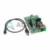 TLE9855EVALKITTOBO1Infineon TechnologiesTLE9855 EVALKIT
 TLE9853QX
 TLE9845APPKITPNTOBO1Infineon TechnologiesTLE9845 APPKIT PN
 TLE9843QXXUMA1Infineon
 TLE9855QX


