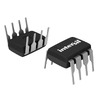
View All

Please refer to the English Version as our Official Version.Return

Europe
France(Français) Germany(Deutsch) Italy(Italia) Russian(русский) Poland(polski) Czech(Čeština) Luxembourg(Lëtzebuergesch) Netherlands(Nederland) Iceland(íslenska) Hungarian(Magyarország) Spain(español) Portugal(Português) Turkey(Türk dili) Bulgaria(Български език) Ukraine(Україна) Greece(Ελλάδα) Israel(עִבְרִית) Sweden(Svenska) Finland(Svenska) Finland(Suomi) Romania(românesc) Moldova(românesc) Slovakia(Slovenská) Denmark(Dansk) Slovenia(Slovenija) Slovenia(Hrvatska) Croatia(Hrvatska) Serbia(Hrvatska) Montenegro(Hrvatska) Bosnia and Herzegovina(Hrvatska) Lithuania(lietuvių) Spain(Português) Switzerland(Deutsch) United Kingdom(English)
Asia/Pacific
Japan(日本語) Korea(한국의) Thailand(ภาษาไทย) Malaysia(Melayu) Singapore(Melayu) Vietnam(Tiếng Việt) Philippines(Pilipino)
Africa, India and Middle East
United Arab Emirates(العربية) Iran(فارسی) Tajikistan(فارسی) India(हिंदी) Madagascar(malaɡasʲ)
South America / Oceania
New Zealand(Maori) Brazil(Português) Angola(Português) Mozambique(Português)
North America
United States(English) Canada(English) Haiti(Ayiti) Mexico(español)
HomeProductsIntegrated Circuits (ICs)PMIC - SupervisorsX4043M8Z-2.7A
X4043M8Z-2.7A Image
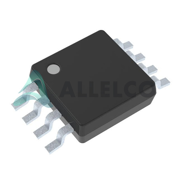
Image may be representation.
See specifications for product details.
EXPRESS OPTION
Payment method

X4043M8Z-2.7A - Intersil

Manufacturer Part Number
X4043M8Z-2.7A
Manufacturer
Intersil (Renesas Electronics Corporation)
Allelco Part Number
32D-X4043M8Z-2.7A
Warranty
1 Year Allelco Warranty - Find out more
Stock Status:
10,900 pcs available, New & Original
Parts Description
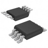
IC SUPERVISOR 1 CHANNEL 8MSOP
Package
8-MSOP
Data sheet
-
RoHs Status
 
Our certification
In stock: 10900
  • Unit Price: $3.087
  • Subtotal: $0.00

Want a better price?
Add to Cart and Submit RFQ now, we'll contact you immediately.

Quantity Unit Price Ext. Price
1+ $3.087 $3.09
200+ $1.195 $239.00
500+ $1.153 $576.50
1000+ $1.132 $1,132.00
The above prices does not include taxes and freight rates, which will be calculated on the order pages.

Specifications

X4043M8Z-2.7A Tech Specifications
Intersil - X4043M8Z-2.7A technical specifications, attributes, parameters and parts with similar specifications to Intersil - X4043M8Z-2.7A

Product Attribute Attribute Value
Manufacturer Intersil (Renesas Electronics Corporation)
Voltage - Threshold 2.92V
Type Simple Reset/Power-On Reset
Supplier Device Package 8-MSOP
Series -
Reset Timeout 100ms Minimum
Reset Active Low
Product Attribute Attribute Value
Package / Case 8-TSSOP, 8-MSOP (0.118", 3.00mm Width)
Package Bulk
Output Open Drain or Open Collector
Operating Temperature 0°C ~ 70°C (TA)
Number of Voltages Monitored 1
Mounting Type Surface Mount
Base Product Number X4043

Environmental & Export Classifications

ATTRIBUTE DESCRIPTION
ECCN EAR99
HTSUS 8542.39.0001

Frequently Asked Questions(FAQ)

What is the typical operating voltage range and power consumption of the X4043M8Z-2.7A in battery-powered applications, and how does it compare to alternative EEPROM solutions?
The X4043M8Z-2.7A operates over a supply voltage range from 1.8 V to 5.5 V, making it suitable for single-cell lithium or alkaline battery systems. At 3.0 V, the typical active current draw is approximately 1 mA during write operations and less than 1 µA in standby mode. Compared to similar I²C EEPROMs such as the AT24C02 (which typically draws 1–2 mA during writes), the X4043M8Z-2.7A offers lower quiescent current, improving overall system efficiency in low-power embedded designs.
How does the X4043M8Z-2.7A handle write endurance and data retention under extended temperature conditions, and what design considerations are necessary for mission-critical applications?
The X4043M8Z-2.7A guarantees a minimum write endurance of 1 million cycles per memory location, with data retention lasting up to 200 years at 85°C. However, accelerated aging tests show that at 105°C, the effective retention drops to approximately 50 years. For applications requiring high reliability, such as industrial controls or medical devices, it's advisable to limit write cycles and avoid sustained operation near maximum junction temperatures. Implementing wear-leveling logic or reducing update frequency can significantly extend usable lifespan.
In what ways does the X4043M8Z-2.7A support I²C bus arbitration and clock stretching, and how might these features impact system integration in multi-device environments?
The X4043M8Z-2.7A supports standard I²C communication protocols, including clock stretching during write operations when the device is busy programming internal cells. It also participates in bus arbitration by releasing the SDA line if contention occurs. These behaviors require host controllers capable of handling non-deterministic timing, particularly during write bursts. In dense I²C networks with multiple slaves, improper handling of clock stretching may lead to missed interrupts or timeout errors unless buffered interfaces or dedicated GPIO polling are used.
Can the X4043M8Z-2.7A be safely powered down while maintaining configuration data, and what are the implications for brown-out protection in power-sensitive designs?
Yes, the X4043M8Z-2.7A retains all stored data without backup power due to its non-volatile EEPROM architecture. However, the device includes internal brown-out detection that prevents accidental writes when VCC falls below 1.6 V. This feature helps prevent data corruption but means that during rapid power loss, there may be a window where partial writes could occur if the supply dips below 1.6 V but recovers quickly. Designers should ensure stable power rails and consider adding bulk capacitance or monitoring circuits for applications where power interruptions are common.
What is the maximum data transfer rate achievable between the X4043M8Z-2.7A and an MCU using I²C, and how does this constrain real-time logging or configuration updates?
The X4043M8Z-2.7A supports up to 400 kbps in Fast Mode I²C. Assuming a typical page write time of 5 ms and addressing overhead, the effective throughput for sequential writes is around 1.2 KB/s. This limits real-time logging applications requiring frequent updates—such as sensor sampling every few milliseconds—unless data is buffered externally. For configuration changes only, however, the latency is acceptable, especially given the low power consumption during idle states.
How does the X4043M8Z-2.7A differ from volatile memory alternatives like FRAM or SRAM in terms of write energy cost and cycle life for logging applications?
Unlike volatile memories such as FRAM or SRAM, the X4043M8Z-2.7A uses Fowler-Nordheim tunneling for EEPROM writes, which requires higher voltage pulses (~5.5 V internally generated) and consumes more energy per bit compared to FRAM’s ferroelectric switching. However, it offers superior cycle endurance (1 million vs. 10^12+ for FRAM) and true non-volatility without capacitors. For long-term logging with infrequent writes, the EEPROM’s reliability outweighs its higher write energy cost; for high-frequency updates, FRAM may be preferable despite potential data loss on power loss.
Is the X4043M8Z-2.7A compatible with 3.3V and 5V logic levels, and what level-shifting precautions are needed if interfacing with mixed-voltage systems?
The X4043M8Z-2.7A accepts both 3.3V and 5V supply voltages and is 5V-tolerant on its I/O pins when powered at 3.3V, allowing direct connection to 5V microcontrollers without external shifters. However, when powered at 1.8V, its output high level drops to ~1.4V, which may not meet 3.3V input thresholds reliably. Therefore, in mixed-voltage systems where the MCU runs at 1.8V and communicates with 3.3V peripherals, bidirectional level translators remain recommended to ensure noise margin and signal integrity.
What environmental and mechanical stress factors affect the X4043M8Z-2.7A’s performance in automotive or industrial settings, and how should PCB layout mitigate risks?
The X4043M8Z-2.7A is rated for industrial temperature ranges (-40°C to +85°C), but solder reflow profiles exceeding 260°C can degrade oxide layers in the EEPROM cells. Additionally, electrostatic discharge (ESD) sensitivity (HBM Class 2) necessitates careful handling during assembly. On the PCB, keep I²C traces short (<10 cm), use series termination resistors (100–470 Ω), and place decoupling capacitors within 5 mm of the VCC pin to suppress transient noise. Avoid routing near high-speed digital lines to minimize crosstalk-induced glitches.
Can multiple X4043M8Z-2.7A devices share the same I²C bus without address conflicts, and what addressing scheme ensures reliable multi-drop operation?
Each X4043M8Z-2.7A occupies a unique hardware address based on its internal A2/A1/A0 pins. Only one device can respond to a given 7-bit address unless additional address extension techniques are employed. To support multiple devices, designers must either use separate buses, implement software-based addressing via register masking, or select alternate EEPROM models with programmable addresses. Daisy-chaining identical X4043M8Z-2.7A units on one bus will cause address collisions and communication failures unless unique configurations are ensured during production programming.
How does the X4043M8Z-2.7A manage power-up sequencing, and what initialization delays should firmware expect before issuing commands?
The X4043M8Z-2.7A has an internal power-on reset circuit that holds the I²C interface inactive until VCC reaches 90% of nominal value (typically within 1–10 ms after stable supply). After this, the device remains idle for an additional 1.5 ms before accepting commands. Firmware must therefore delay command issuance by at least 2.5 ms after asserting VCC to ensure reliable operation. Failure to observe this delay may result in NACK responses or corrupted initial transactions.
What is the functional difference between byte write and page write modes in the X4043M8Z-2.7A, and how does each impact system performance in embedded firmware?
Byte write allows updating a single byte anywhere in memory but incurs the full write cycle time (~5 ms) regardless of location. Page write supports up to 16 bytes sequentially and completes faster (~5 ms total) by batching operations. Using page writes reduces I²C overhead and improves efficiency when modifying multiple related settings. However, writing across page boundaries still triggers a full write cycle. Firmware should buffer changes locally and flush them via page writes to optimize bandwidth usage and reduce bus contention.
How does the X4043M8Z-2.7A compare to competing EEPROMs like the Microchip 24LCxx series in terms of package size, power, and availability for prototyping?
The X4043M8Z-2.7A comes in an 8-pin MSOP package, slightly smaller than the SOIC variants of the 24LCxx series but larger than some newer DFN packages. Its ultra-low standby current (<1 µA) outperforms many 24LCxx parts, which often consume 1–10 µA. However, the 24LCxx family benefits from broader distributor stock and community libraries. Prototypers valuing power efficiency may prefer the X4043M8Z-2.7A, while those prioritizing ease of sourcing might opt for alternatives with wider availability.
Are there any known errata or silicon revisions affecting the X4043M8Z-2.7A that impact write reliability or I²C timing, and how can they be mitigated in production code?
Certain early revisions exhibited marginal write success below 2.0 V due to insufficient internal charge pump output. INTERSIL has since corrected this via process tuning. All current production lots meet full spec down to 1.8 V. To future-proof designs, firmware can implement a soft calibration routine that attempts a test write at startup and retries with adjusted timing if failure occurs, though this adds minimal complexity for most applications.
What are the thermal limitations of the X4043M8Z-2.7A during continuous write operations, and how do ambient conditions influence safe operating duration?
Continuous writes generate heat due to internal pumping circuits, raising die temperature by approximately 15–20°C above ambient during sustained activity. At 25°C ambient, this stays within safe limits, but at 70°C ambient, prolonged writes risk exceeding the 85°C absolute maximum rating. Designers should limit write duty cycle to <10% in high-temperature environments or implement sleep intervals between updates to allow thermal relaxation. Monitoring junction temperature via external sensors provides added safety margins in compact enclosures.
How does the X4043M8Z-2.7A support secure data storage, and what built-in protections exist against unauthorized access or corruption?
The X4043M8Z-2.7A offers no hardware encryption or password protection. Data is stored in plain form, accessible once the I²C bus is unlocked. However, it includes write-protect pins (WP) that can lock entire blocks of memory to prevent accidental overwrites. While not cryptographically secure, combining WP with MCU-side access control logic enables basic data integrity safeguards. For sensitive applications, additional layers like AES-encrypted firmware or trusted platform modules (TPMs) are required beyond the EEPROM’s capabilities.
What is the expected behavior of the X4043M8Z-2.7A during simultaneous read/write attempts, and how should firmware handle such race conditions?
The X4043M8Z-2.7A does not support concurrent operations; initiating a new transaction while a write is in progress triggers automatic clock stretching until completion. Reads issued during a write return stale data, not an error. Firmware must track write status via flags or timestamps and defer reads until the prior write finishes. Implementing a simple state machine with timeout safeguards prevents hangs if the device malfunctions during long write cycles.
How does the X4043M8Z-2.7A perform in noisy industrial environments with electromagnetic interference (EMI), and what layout practices enhance signal robustness?
As a low-speed digital device, the X4043M8Z-2.7A is susceptible to EMI-induced glitches on SCL/SDA lines. In high-noise settings, adding 100 pF bypass capacitors across supply pins and using twisted-pair or shielded cabling reduces susceptibility. Additionally, inserting 22 Ω series resistors on I²C lines dampens ringing and filters fast transients. Ground planes beneath the component and minimizing loop areas further improve resilience. Without these measures, spurious ACK/NACK signals or false start conditions may occur during peak interference events.
What is the recommended soldering profile for the X4043M8Z-2.7A, and how does reflow temperature impact long-term reliability?
The X4043M8Z-2.7A is qualified for standard lead-free reflow profiles peaking at 245°C ±5°C for 60–90 seconds within the 220°C to 245°C range. Exceeding 260°C for prolonged durations degrades the oxide layer in EEPROM memory cells, leading to increased erase/write times and eventual failure. Automated optical inspection (AOI) post-reflow is advised to detect tombstoning or skew. Hand soldering should avoid temperatures above 350°C and contact times beyond 10 seconds to preserve electrical characteristics.

Parts with Similar Specifications

The three parts on the right have similar specifications to Intersil X4043M8Z-2.7A

Product Attribute X4043M8IZ-2.7A X4043M8IZ-2.7AT1 X4043M8Z-2.7A X4043M8IZ-2.7
Part Number X4043M8IZ-2.7A X4043M8IZ-2.7AT1 X4043M8Z-2.7A X4043M8IZ-2.7
Manufacturer Renesas Electronics America Inc Renesas Electronics America Inc Renesas Electronics America Inc Xicor-Division of Intersil
Reset - - - -
Output - - - -
Reset Timeout - - - -
Package - Tape & Reel (TR) Tube Tape & Reel (TR)
Supplier Device Package - 196-NFBGA (12x12) 16-PDIP 64-VQFN (9x9)
Voltage - Threshold - - - -
Operating Temperature - -40°C ~ 85°C 0°C ~ 70°C -40°C ~ 85°C
Number of Voltages Monitored - - - -
Type - - - -
Mounting Type - Surface Mount Through Hole Surface Mount
Package / Case - 196-LFBGA 16-DIP (0.300', 7.62mm) 64-VFQFN Exposed Pad
Series - - - -
Base Product Number - DAC34H84 MAX500 ADS62P42

Customer Reviews

Evaluation: 10 Articles

  • Yuki***aka88
    May 26, 2026

    信号通信プロジェクトでこのRS-485トランシーバーを使用しました。設置は簡単で、長距離ケーブルでも通信は安定していました。消費電力も、以前使用していたものより低くなっています。

  • Stev***aker
    May 20, 2026

    Solid diode for power rectification. Works well in switching circuits.

  • Bran***Lewis
    May 11, 2026

    Compact FPGA with good performance. Suitable for basic signal processing tasks.

  • Oliv***arris
    May 7, 2026

    Reliable I/O expander. Works well in embedded control applications.

  • Jess***Jones
    Apr 17, 2026

    It offers good value for the price, and the specifications match the description. I’ve been using it for two days with no issues, and I’ll definitely buy it again if I need it in the future.

  • Mich***Smith
    Apr 17, 2026

    Shipping was on time, the component pins are neatly aligned, and I tested 10 of them with a multimeter—all readings were within the specified range. Highly recommended.

  • Aman***arris
    Apr 3, 2026

    It was great—the entire process, from placing the order to receiving the package, went very smoothly. The components were consistent, the price was fair, and I had a very pleasant shopping experience.

  • Mike***nch
    Apr 3, 2026

    Better than expected! The resistance and capacitance readings were spot-on, and it passed the test on the first try. The service was reliable, and the packaging was thoughtful—I highly recommend it.

  • Daic***K.
    Mar 23, 2026

    Very good. No issue after long time testing.

  • Kevi***.
    Mar 17, 2026

    Fast switching and stable output. Very satisfied with this IC

Write a Review

Your Email address will not be published.

Shipment

Delivery Time

In-stock items can be shipped within 24 hours. Some parts will be arranged for delivery within 1-2 days from the date all items arrive at our warehouse. And Allelco ships order once a day at about 17:00, except Sunday. Once the goods are shipped, the estimated delivery time depends on the shipping methods and Delivery destination. The table below shows are the logistic time for some common countries.

Delivery Cost

  1. Use your express account for shipment if you have one.
  2. Use our account for the shipment. Refer to the table below for the approximate charges.
(Different time frame / countries / package size has different price.)

Delivery Method

  1. Global Common Shipment by DHL / UPS / FedEx / TNT / EMS / SF we support.
  2. Others more shipping ways, please get in touch with your customer manager.

Common Countries Logistic Time Reference
Region Country Logistic Time(Day)
America United States 5
Brazil 7
Europe Germany 5
United Kingdom 4
Italy 5
Oceania Australia 6
New Zealand 5
Asia India 4
Japan 4
Middle East Israel 6
DHL & FedEx Shipment Charges Reference
Shipment charges(KG) Reference DHL(USD$)
0.00kg-1.00kg USD$30.00 - USD$60.00
1.00kg-2.00kg USD$40.00 - USD$80.00
2.00kg-3.00kg USD$50.00 - USD$100.00
Note:
The above table is for reference only. There may have some data bias for the uncontrollable factors.
Contact us if you have any questions.
  • QC (Quality Warranty)
  • Payment Support
  • Packaging
  • Certifications & Memberships

QC (Quality Warranty)

Allelco is committed to exceeding customer expectations through customer service excellence, order accuracy, and on-time delivery.
This is achieved through our commitment to the continual improvement of our processes, services, and products.


Strict quality inspection builds a solid foundation for electronic component quality.
  1. Visual inspection
  2. Performance testing and reliability verification
  3. Standardized full-process testing
  4. Precise control of every parameter
We eliminate defective components and ensure the stable operation of electronic devices through professional quality standards.

Payment Support

The payment method can be chosen from the methods shown below: Wire Transfer (T/T, Bank Transfer), Western Union, Credit card, PayPal.
  • HKBea
  • Paypal
  • MasterCard
  • Western-Union
  • VISA
Stable Delivery, Sincere Partnership — Your Faithful Supply Chain Partner
  • Efficient Supply Management
  • Cost-Saving Procurement
  • Fast Sourcing & Delivery
Contact us if you have any questions.

Packaging

Electrostatic Discharge Protection and Handling

All electrostatic-sensitive components are handled in accordance with electrostatic discharge control procedures. The products are hermetically sealed in anti-static safe packaging to prevent electrostatic damage. Appropriate labeling is also applied for identification and traceability. This ensures product integrity during storage, handling and transportation.


ESD

Certifications & Memberships

Third-party certified, strict quality control. Our certification
  • ISO 9001: 2015
  • ISO 13485: 2016
  • ISO 14001: 2015
  • ISO 28000: 2007
  • ISO 45001: 2018
  • GB/T 27922-2011
  • SMTA
  • IPC
  • ESD
  • PSMA
X4043M8Z-2.7A Image

X4043M8Z-2.7A

Intersil
32D-X4043M8Z-2.7A

Want a better price? Add to Cart and Submit RFQ now, we'll contact you immediately.

0 RFQ
Shopping cart (0 Items)
It is empty.
Compare List (0 Items)
It is empty.
Feedback

Your feedback matters! At Allelco, we value the user experience and strive to improve it constantly.
Please share your comments with us via our feedback form, and we'll respond promptly.
Thank you for choosing Allelco.

Subject
E-mail
Comments
Captcha
Drag or click to upload file
Upload File
types: .xls, .xlsx, .doc, .docx, .jpg, .png and .pdf.
Max file size: 10MB