
74ACT16245DGGR (1)
Manufacturer Part Number
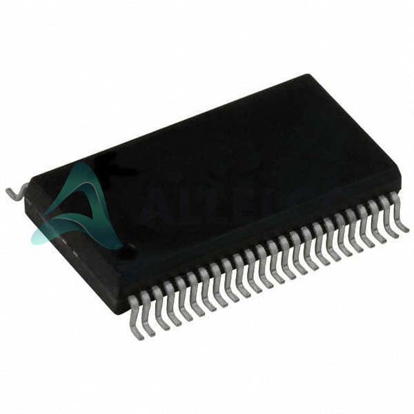
74ACT16245DGGR
Manufacturer
Texas Instruments
Introduction
High-speed CMOS transceiver offering bidirectional communication between two buses
Product Features and Performance
Supports bidirectional data flow
Logic Type: Transceiver, Non-Inverting
Number of Elements: 2
Number of Bits per Element: 8
Output Type: 3-State, enabling bidirectional communication
Operates from 4.5V to 5.5V
Product Advantages
Enhanced high-speed data transfer
Low power consumption
Designed for minimal propagation delay
Key Technical Parameters
Voltage - Supply: 4.5V ~ 5.5V
Current - Output High, Low: 24mA
Operating Temperature Range: -40°C ~ 85°C
Mounting Type: Surface Mount
48-TFSOP Package, providing a compact footprint
Quality and Safety Features
Built to adhere to stringent quality standards
Suitable for industrial temperature ranges
Reliable performance in harsh conditions
Compatibility
Compatible with TTL logic levels
Multiple bus management
Application Areas
Telecommunications
Data processing
Consumer electronics
Control systems
Product Lifecycle
Product Status: Active
Not near discontinuation
Replacements and upgrades available
Several Key Reasons to Choose This Product
Robust supply voltage range catering to typical logic level requirements
Optimized for low-power operation and high-speed performance
Flexible usage across a wide range of applications due to 3-State outputs
Proven reliability given Texas Instruments' reputation in the industry
Available in Tape & Reel for automated assembly processes


 74ACT16245DLRTexas InstrumentsIC TXRX NON-INVERT 5.5V 48SSOP
 74ACT16244SSCFairchild SemiconductorIC BUFFER NON-INVERT 5.5V 48SSOP
 74ACT16244SSCXonsemiIC BUF NON-INVERT 5.5V 48SSOP
 74ACT16244MTDXFairchild SemiconductorIC BUFF NON-INVERT 5.5V 48TSSOP


