
Manufacturer Part Number
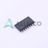
AM26LV31CNSR
Manufacturer
Texas Instruments
Introduction
The AM26LV31CNSR is a 4-bit, high-speed, balanced line driver designed for RS-422 and RS-485 communications. It is well-suited for applications requiring high-speed data transmission over long distances or in noisy environments.
Product Features and Performance
4-bit line driver
High-speed operation up to 10 Mbps
Supports RS-422 and RS-485 interfaces
Differential driver outputs for high noise immunity
Slew-rate limited outputs for EMI reduction
Thermal shutdown protection
3V to 3.6V supply voltage range
Operates from 0°C to 70°C
Product Advantages
Robust RS-422 and RS-485 communication support
High-speed data transmission over long distances
Excellent noise immunity for reliable operation
Thermal shutdown protection for safety
Wide operating voltage and temperature range
Key Technical Parameters
Number of Drivers/Receivers: 4/0
Protocol: RS-422, RS-485
Driver Type: Balanced line driver
Supply Voltage: 3V to 3.6V
Operating Temperature: 0°C to 70°C
Quality and Safety Features
RoHS3 compliant
Thermal shutdown protection
Compatibility
The AM26LV31CNSR is compatible with a variety of RS-422 and RS-485 communication systems.
Application Areas
Industrial automation and control systems
Telecommunications equipment
Medical devices
Transportation systems
Security and surveillance systems
Product Lifecycle
The AM26LV31CNSR is an active product and is not nearing discontinuation. Replacement or upgrade options are available from Texas Instruments.
Key Reasons to Choose This Product
Robust RS-422 and RS-485 communication support
High-speed data transmission up to 10 Mbps
Excellent noise immunity for reliable operation
Wide operating voltage and temperature range
Thermal shutdown protection for safety
RoHS3 compliance for environmental responsibility

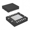 AM26LV31EIRGYRTexas InstrumentsIC DRIVER 4/0 16VQFN
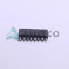
 AM26LV31EIPWRTexas InstrumentsIC DRIVER 4/0 16TSSOP
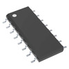
 AM26LV31CDTexas InstrumentsIC DRIVER 4/0 16SOIC
 AM26LV31EIDRTexas InstrumentsIC DRIVER 4/0 16SOIC
 AM26LV31EIPWTexas Instruments


