
BQ24075TRGTR (1)
Manufacturer Part Number
BQ24075TRGTR
Manufacturer
Texas Instruments
Introduction
The BQ24075TRGTR is a highly integrated battery charger designed for charging lithium-ion cells, ideal for portable devices demanding power management solutions.
Product Features and Performance
Designed for single-cell lithium-ion batteries
Programmable charge current up to 1.5A
Supports USB interface for charging
Integrated fault protection for over temperature, over voltage, reverse current, and short circuit
Operating temperature range from 0°C to 125°C
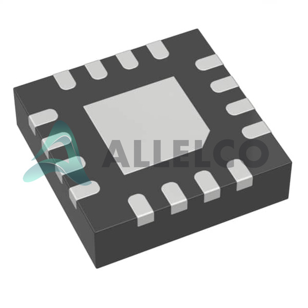
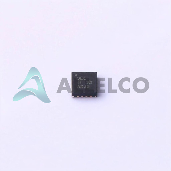
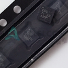
Mounting type: Surface Mount
Package type: 16-VFQFN Exposed Pad
Product Advantages
High charge current capability enhances quick charging
Programmable features allow customization according to application needs
Comprehensive fault protection improves safety and extends product life
BQ24075TRGTR (2)
Key Technical Parameters
Battery Chemistry: Lithium Ion
Number of Cells: 1
Charge Current Max: 1.5A
Battery Pack Voltage: 4.2V
Voltage Supply (Max): 6.4V
Quality and Safety Features
Over temperature protection
Over voltage protection
Reverse current protection
Short circuit protection
Compatibility
Compatible with USB-powered devices for charging
Suitable for various single-cell lithium-ion battery applications
Application Areas
Portable consumer electronics
Power banks
Handheld devices
Product Lifecycle
Currently in Active status
Not nearing discontinuation, ensuring ongoing availability
Upgrades and replacements readily available
Several Key Reasons to Choose This Product
High charging capability for faster recharge times
Customizable charging parameters for diverse applications
Robust fault protection features ensure reliability and safety
Wide operating temperature range suitable for various environments
Active product lifecycle stage with Texas Instruments' support and availability


 BQ24075RGTTTexas InstrumentsIC BATT CHG LI-ION 1CELL 16QFN
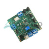 BQ24078EVM-015Texas InstrumentsEVAL BOARD FOR BQ24078
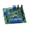 BQ24075TEVMTexas InstrumentsEVAL MODULE FOR BQ24075T
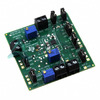 BQ24075EVMTexas InstrumentsEVAL MODULE FOR BQ24075
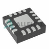 BQ24079QWRGTTQ1Texas InstrumentsIC BATT CHG LI-ION 1CELL 16VQFN
 BQ24078RGTRTexas InstrumentsIC BATT CHG LI-ION 1CELL 16VQFN
 BQ24076RGTRTexas InstrumentsIC BATT CHG LI-ION 1CELL 16VQFN


