

LM5175RHFT (1)
Manufacturer Part Number
LM5175RHFT
Manufacturer
Texas Instruments
Introduction
The LM5175RHFT is a versatile DC DC switching controller from Texas Instruments designed to manage power through step-up and step-down functionality, suitable for a broad range of voltage supply conditions.
Product Features and Performance
Operates from input voltages of 3.5V to 42V
Buck-Boost topology ensures efficient voltage conversion for step-up or step-down conditions
Supports output in the form of Transistor Driver
Frequency switching ranges from 100kHz to 600kHz
Embedded Synchronous Rectifier for enhanced efficiency
Clock synchronization available
Multiple control features including Enable, Frequency Control, Power Good, and Soft Start
Product Advantages
Flexible supply voltage range accommodates varied power needs
High conversion efficiency due to synchronous rectification
Adjustable frequency allows optimization for specific applications
Enhanced system reliability with built-in protective control features
Key Technical Parameters
Voltage Supply (Vcc/Vdd): 3.5V ~ 42V
Switching Frequency: 100kHz ~ 600kHz
Output Configuration: Positive
Topology: Buck-Boost
Temperature: Operating between -40°C ~ 125°C
Quality and Safety Features
Operating Temperature rated for industrial thermal extremes
Robust against voltage fluctuations within specified ranges
Built to meet stringent safety and quality standards of the electronics industry
Compatibility
Compatible with a wide range of input voltage levels for versatile applications
Suitable for various output load conditions due to adjustable performance specifications
Application Areas
Industrial systems
Power management solutions in automotive and telecommunication
Energy harvesting systems
Portable electronic devices requiring efficient power conservation profiles
Product Lifecycle
Currently active in production with no announced plans for discontinuation
Upgrades and replacements are available under Texas Instruments' extensive power management portfolio
Several Key Reasons to Choose This Product
High efficiency with synchronous rectification technology which minimizes energy loss
Versatile operating conditions compatible with a range of industrial applications
Reliable operation in extreme temperatures and volatile power environments
Ability to handle both step-up and step-down voltage requirements simplifies system design
Support from a reputable manufacturer, Texas Instruments, with a strong track record in power management solutions

 LM5176PWPRTexas InstrumentsLM5176PWPR
 LM5175QPWPTQ1Texas InstrumentsIC REG CTRLR BUCK-BOOST 28HTSSOP
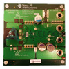 LM5176EVM-HPTexas InstrumentsEVAL BOARD FOR LM5176
 LM5176QPWPTQ1Texas Instruments.5-55VIN 4 SWITCH BUCK-BOOST CON
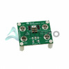 LM5175RHFEVM-HDTexas InstrumentsEVAL BOARD FOR LM5175
 LM5176QPWPRQ1Texas InstrumentsIC POWER REGULATOR
 LM5176PWPTTexas Instruments.5-55VIN 4 SWITCH BUCK-BOOST CON
 LM5176


