


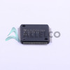
MSP430F5328IRGCR (1)
Manufacturer Part Number
MSP430F5328IRGCR
Manufacturer
Texas Instruments
Introduction
16-bit ultra-low-power microcontroller
Product Features and Performance
25MHz operating speed
128KB flash program memory
10KB RAM
12-bit ADC
IrDA, LINbus, SCI, SPI, UART/USART connectivity
Brown-out detection and reset
DMA, power-on reset, PWM, watchdog timer peripherals
Operating voltage range: 1.8V to 3.6V
Operating temperature range: -40°C to 85°C
Product Advantages
Extremely low power consumption
Robust connectivity and peripheral options
Flexible memory and performance configurations
Wide operating temperature range

MSP430F5328IRGCR (2)
Key Technical Parameters
16-bit MSP430 core
25MHz maximum clock speed
128KB flash program memory
10KB RAM
12-bit ADC
Quality and Safety Features
RoHS3 compliant
Brown-out detection and reset
Watchdog timer for system integrity
Compatibility
Suitable for a wide range of embedded applications
Application Areas
Industrial automation
Portable medical devices
Metering and instrumentation
Home and building automation
Wireless sensor networks
Product Lifecycle
Current product, no discontinuation planned
Replacement/upgrade options available within the MSP430 family
Several Key Reasons to Choose This Product
Exceptional power efficiency for battery-powered applications
Extensive connectivity and peripherals for versatile design
Robust temperature range for industrial and harsh environments
Mature and well-supported microcontroller platform from Texas Instruments

 MSP430F5327IPNRTexas Instruments
 MSP430F5328IZXHTexas InstrumentsIC MCU 16BIT 128KB FLASH 80NFBGA
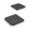 MSP430F5333IPZTexas InstrumentsIC MCU 16BIT 128KB FLASH 100LQFP


