

OPA4192IDR (1)
Manufacturer Part Number
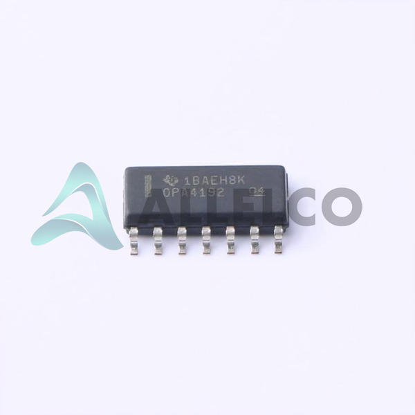
OPA4192IDR
Manufacturer
Texas Instruments
Introduction
The OPA4192IDR is a quad operational amplifier (op-amp) from Texas Instruments. It is part of the MicroAmplifier series and is designed for a wide range of general-purpose amplifier applications.
Product Features and Performance
Quad op-amp in a single package
10 MHz gain-bandwidth product
Rail-to-rail output
Low input offset voltage of 5 μV
Low input bias current of 5 pA
Slew rate of 20 V/μs
Wide supply voltage range from 4.5 V to 36 V
Capable of driving up to 65 mA per channel
Operating temperature range of -40°C to +125°C
Product Advantages
Compact quad op-amp design for space-constrained applications
Excellent DC and AC performance for precise and stable amplification
Wide operating voltage range for versatile power supply requirements
Suitable for a variety of general-purpose amplifier applications
OPA4192IDR (2)
Key Technical Parameters
Manufacturer Part Number: OPA4192IDR
Package: 14-SOIC (0.154", 3.90mm Width)
Number of Circuits: 4
Gain Bandwidth Product: 10 MHz
Voltage Supply Span (Min/Max): 4.5 V to 36 V
Current Supply: 1 mA per channel
Slew Rate: 20 V/μs
Voltage Input Offset: 5 μV
Amplifier Type: General Purpose
Current Output / Channel: 65 mA
Current Input Bias: 5 pA
Quality and Safety Features
RoHS3 compliant
Surface mount package for reliable assembly
Compatibility
Suitable for a wide range of general-purpose amplifier applications
Application Areas
Instrumentation and measurement equipment
Data acquisition systems
Industrial control and automation
Audio and video signal processing
Product Lifecycle
Currently in active production
Replacements and upgrades may be available in the future
Key Reasons to Choose This Product
Compact quad op-amp design for efficient use of board space
Excellent DC and AC performance for precise and stable amplification
Wide operating voltage range for versatile power supply requirements
Suitable for a variety of general-purpose amplifier applications
RoHS3 compliance for environmental responsibility
 OPA4192IDTexas InstrumentsIC OPAMP GP 4 CIRCUIT 14SOIC
 OPA4191IPWTTexas InstrumentsIC OPAMP
 OPA4191IRUMTTexas InstrumentsIC CMOS 4 CIRCUIT 16WQFN
 OPA4192IPWTexas InstrumentsIC OPAMP GP 4 CIRCUIT 14TSSOP
 OPA4191IPWRTexas Instruments
 OPA4192IDRG4TI/BB


