

OPA695IDR (1)
Manufacturer Part Number
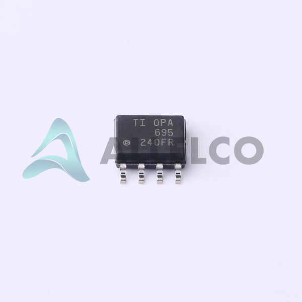
OPA695IDR
Manufacturer
Texas Instruments
Introduction
High-speed, high-drive, current-feedback operational amplifier for instrumentation and buffer applications.
Product Features and Performance
Slew rate of 4300V/s
Bandwidth of 1.7GHz
Supply voltage range of 5V to 12V
Low input offset voltage of 300μV
High output current capability of 120mA
Wide operating temperature range of -40°C to 85°C
Product Advantages
Excellent high-frequency performance
High-speed and high-drive capabilities
Versatile for a wide range of applications
OPA695IDR (2)
Key Technical Parameters
Manufacturer Part Number: OPA695IDR
Package: 8-SOIC
Mounting Type: Surface Mount
Operating Temperature: -40°C to 85°C
Quality and Safety Features
RoHS3 compliant
Tape and reel packaging for reliable delivery
Compatibility
Suitable for instrumentation and buffer applications
Application Areas
Instrumentation
High-speed buffer circuits
High-frequency amplifier designs
Product Lifecycle
Currently in production
Replacement and upgrade options available from Texas Instruments
Several Key Reasons to Choose This Product
Excellent high-frequency performance with 1.7GHz bandwidth
High slew rate of 4300V/s for fast signal handling
Versatile for a wide range of instrumentation and buffer applications
Wide operating temperature range of -40°C to 85°C
RoHS3 compliance for environmental sustainability


 OPA698IDRTexas InstrumentsIC VOLTAGE FEEDBACK 1 CIRC 8SOIC
 OPA695IDGKTTexas Instruments
 OPA698MJDTexas InstrumentsOPA698M UNITY-GAIN-STABLE WIDEBA


