
TLC320AC02IPM (1)
Manufacturer Part Number
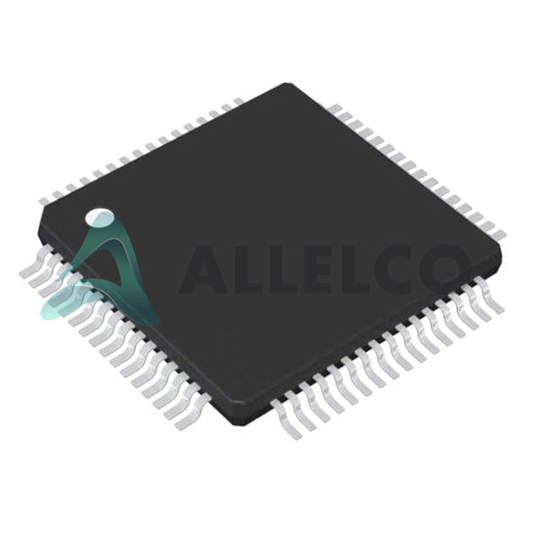
TLC320AC02IPM
Manufacturer
Texas Instruments
Introduction
The TLC320AC02IPM is an audio interface codec designed for efficient audio signal processing and transmission.
Product Features and Performance
Audio interface codec
14-bit resolution
Serial data interface
Single ADC/DAC
Surface mount, 64-LQFP package
Operates from 4.5V to 5.5V for both analog and digital supply
Suitable for temperatures ranging from -40°C to 85°C
Product Advantages
Optimized for high-definition audio applications
Compact 64-LQFP packaging ideal for space-constrained applications
Key Technical Parameters
Resolution: 14 bits
ADCs/DACs: 1/1
Supply Voltage, Analog and Digital: 4.5V ~ 5.5V
Operating Temperature: -40°C ~ 85°C
Quality and Safety Features
Designed to operate reliably in extreme temperatures from -40°C to 85°C
Compatibility
Compatible with various microcontrollers and processors through its serial interface
Application Areas
Audio processing equipment
Telecommunication systems
Product Lifecycle
Status: Active
This product is currently in active production with no announced discontinuation. Replacement or upgrade models are available.
Several Key Reasons to Choose This Product
High-resolution audio processing capability
Stable operation across a wide range of supply voltages and temperatures
Compact and reliable design suitable for various applications
Direct compatibility with a range of serial interface microcontrollers and processors.


 TLC320AD50CPTRTexas InstrumentsIC CODEC 16BIT SER 48-LQFP
 TLC320AD50CDWRTexas InstrumentsIC CODEC 16BIT SER 28SOIC


