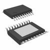
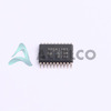
TPS61195RUYR (1)
Manufacturer Part Number
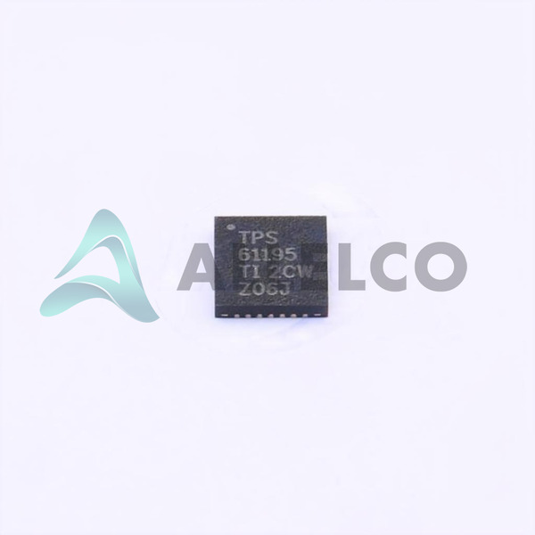
TPS61195RUYR
Manufacturer
Texas Instruments
Introduction
The TPS61195RUYR is a power management integrated circuit (PMIC) designed specifically for LED driving applications, featuring an efficient step-up (boost) topology with internal switches.
Product Features and Performance
Integrated step-up (boost) DC DC regulator
Supports up to 8 LED outputs
High-frequency operation at 1MHz
PWM dimming capability
Built-in thermal shutdown and over-voltage protection
Low quiescent current
High efficiency power conversion
Product Advantages
Offers high-efficiency LED driving solution
Supports a wide range of input voltages from 4.5V to 21V
Flexible output voltage range suitable for various LED configurations (4.5V ~ 45V)
Multi-channel support for complex LED designs
Enhances system safety with integrated protective features
TPS61195RUYR (2)
Key Technical Parameters
Number of Outputs: 8
Min/Max Supply Voltage: 4.5V to 21V
Output Voltage Range: 4.5V ~ 45V
Current per Output Channel: 30mA
Switching Frequency: 1MHz
Quality and Safety Features
Thermal shutdown
Over-voltage protection
Current limit
Under voltage lockout (UVLO)
Compatibility
Designed for compatibility with a wide range of backlight LED configurations
Application Areas
LED backlighting for LCD displays in televisions, computer monitors, and automotive instrumentation
Product Lifecycle
Active product status (not nearing discontinuation)
Availability of replacements or upgrades should be verified directly with Texas Instruments or authorized distributors
Several Key Reasons to Choose This Product
High integration reduces system complexity and bill of materials
Industry-leading power management company (Texas Instruments)
Robust design suitable for extended temperature range applications: -40°C ~ 85°C
Tape & Reel packaging for automated manufacturing processes
The device's reliability and technical support from Texas Instruments


 TPS61197EVMTexas InstrumentsEVAL MODULE FOR TPS61197
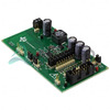 TPS61199EVM-598Texas InstrumentsEVAL MODULE FOR TPS61199-598
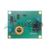
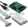 TPS61195EVM-460Texas InstrumentsEVAL MODULE FOR TPS61195
 TPS61197DRTexas InstrumentsIC LED DRIVER CTRLR PWM 16SOIC
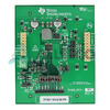 TPS61194Q1EVMTexas InstrumentsEVALUATION MODULE
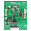 TPS61194EVMTexas InstrumentsEVALUATION MODULE
 TPS61196PWPRTexas InstrumentsIC LED DRVR CTRLR PWM 28HTSSOP
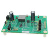 TPS61196EVM-600Texas InstrumentsEVAL BOARD LED DRIVER TPS61196
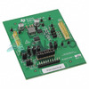 TPS61193Q1EVMTexas InstrumentsEVALUATION MODULE
 TPS61194PWPRQTexas Instruments


