
TPS65251-3RHAR (1)
Manufacturer Part Number
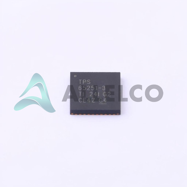
TPS65251-3RHAR
Manufacturer
Texas Instruments
Introduction
The TPS65251-3RHAR is a highly integrated, three-channel, synchronous step-down DC/DC converter from Texas Instruments. It provides a high-efficiency, adjustable power solution with a wide input voltage range, suitable for a variety of power-sensitive applications.
Product Features and Performance
Three independent, adjustable step-down converters
Wide input voltage range: 4.5V to 18V
Adjustable output voltage from 0.8V to 17V
Output current up to 3A, 2A per channel
Switching frequency range of 300kHz to 2.2MHz
Synchronous rectification for high efficiency
Thermal shutdown and overcurrent protection
Product Advantages
High efficiency and power density
Flexible output voltage configuration
Compact 40-pin VFQFN package
Excellent thermal performance
Key Reasons to Choose This Product
Comprehensive power management solution in a single chip
Wide input voltage range accommodates diverse applications
Adjustable output voltage and current allows for customization
Robust protection features ensure reliable operation
Quality and Safety Features
Thermal shutdown and overcurrent protection
Meets industrial temperature range requirements (-40°C to 125°C)
RoHS-compliant and lead-free package
Compatibility
The TPS65251-3RHAR is compatible with a wide range of electronic devices and systems that require multiple, adjustable power rails.
Application Areas
Portable electronics
Industrial automation and control systems
Telecommunications equipment
Automotive electronics
Product Lifecycle
The TPS65251-3RHAR is an active and currently available product. There are no known plans for discontinuation at this time. offers a range of similar and alternative products, including the TPS65250, TPS65251-1, and TPS65251-2, which may be worth considering based on your specific power requirements and design needs. For more information or assistance in selecting the most suitable product, please contact our website's sales team.
 TPS652510EVMTexas InstrumentsEVAL MODULE FOR TPS652510
 TPS65251RHARTexas InstrumentsIC REG BCK ADJ 3A/2A TRPL 40VQFN
 TPS65251EVMTexas InstrumentsEVAL MODULE FOR TPS65251
 TPS65250RHATTexas InstrumentsIC REG BCK ADJ 3A/2A TRPL 40VQFN
 TPS652510RHARTexas InstrumentsIC REG BCK ADJ 3A/2A TRPL 40VQFN
 TPS65250RHARTexas InstrumentsIC REG BCK ADJ 3A/2A TRPL 40VQFN
 TPS65251-1RHARTexas InstrumentsIC REG BCK ADJ 3A/2A TRPL 40VQFN
 TPS652510RHATTexas Instruments


