
Manufacturer Part Number
UCC2805DTRG4
Manufacturer
Texas Instruments
Introduction
The UCC2805DTRG4 is a high-performance, low-power PWM controller designed for a wide range of power supply applications. It features advanced control mechanisms, robust protection features, and high efficiency to deliver reliable and consistent power management capabilities.
Product Features and Performance
Wide input voltage range from -0.3V to 6.3V
Supply voltage range of 3.6V to 11V
Low supply current of 500 μA
Wide operating temperature range of -40°C to 125°C
Surface mount, 8-SOIC package
Capable of driving high-side and low-side N-channel MOSFETs
Product Advantages
Excellent power conversion efficiency
Robust protection features, including overcurrent, overvoltage, and thermal shutdown
Flexible control and configuration options
Compact and space-saving design
Key Reasons to Choose
High performance and reliability in a wide range of power supply applications
Optimized for efficient and stable power management
Comprehensive protection features ensure safe and reliable operation
Small form factor and easy integration into various system designs
Quality and Safety Features
Designed and manufactured to high-quality standards
Robust protection mechanisms for safe and reliable operation
RoHS-compliant and environmentally friendly
Compatibility
The UCC2805DTRG4 is compatible with a variety of power supply and control applications, including:
Switching power supplies
DC-DC converters
Voltage regulators
Industrial and consumer electronics
Application Areas
Power supplies for industrial equipment
Power management in consumer electronics
Automotive and transportation applications
Telecommunications and networking equipment
Product Lifecycle
The UCC2805DTRG4 has been discontinued by the manufacturer, Texas Instruments. However, there are alternative products available that may offer similar or improved features and performance. Customers are advised to contact our website's sales team for more information on comparable products and availability.
 UCC2805NTexas InstrumentsIC REG CTRLR MULT TOPOLOGY 8DIP
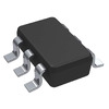 UCC28056CDBVTTexas InstrumentsISOLATED DRIVER
 UCC2805DTRTexas InstrumentsIC REG CTRLR MULT TOPOLOGY 8SOIC
 UCC28056EVM-296Texas InstrumentsEVALUATION MODULE
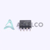 UCC2805QDRQ1Texas InstrumentsIC REG CTRLR MULT TOPOLOGY 8SOIC
 UCC28056DBVRTexas InstrumentsIC PFC CTRLR TRANSITION SOT23-6
 UCC28056CDBVRTexas InstrumentsIC POWER MANAGEMENT
 UCC2805PWTexas InstrumentsIC REG CTRLR MULT TOP 8TSSOP
 UCC28056DBVTTexas InstrumentsIC PFC CTRLR TRANSITION SOT23-6
 UCC2805QDRHTG4Texas Instruments
 UCC2805QDRHTTIPB-FREE


