
ATMEGA88V-10AU (1)
Manufacturer Part Number
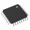
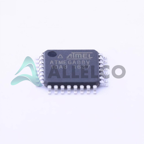
ATMEGA88V-10AU
Manufacturer
Microchip Technology
Introduction
ATMEGA88V-10AU is an 8-bit high-performance microcontroller from the AVR ATmega series designed to offer a balance of power efficiency and processing capability.
Product Features and Performance
Core Processor: AVR
Core Size: 8-Bit
Speed: 10MHz
Connectivity options include I2C, SPI, UART/USART
Peripherals include Brown-out Detect/Reset, POR, PWM, WDT
Number of I/O: 23
Program Memory Size: 8KB (4K x 16)
Program Memory Type: FLASH
EEPROM Size: 512x8
RAM Size: 1Kx8
Voltage Supply: 1.8V to 5.5V
Data Converters: A/D 8x10b
Oscillator Type: Internal
Operational Temperature range: -40°C to 85°C
Product Advantages
Offers robust interface options
Flexible voltage supply range
Equipped with advanced control and safety peripherals
ATMEGA88V-10AU (2)
Key Technical Parameters
Speed: 10MHz
Program Memory: 8KB FLASH
I/O number: 23
Voltage - Supply: 1.8V ~ 5.5V
Data Converter: A/D 8x10b
EEPROM: 512x8
RAM: 1Kx8
Quality and Safety Features
Incorporates Brown-out Detect/Reset and Power-on Reset
Watchdog Timer for system stability
Compatibility
Compatible with various communication protocols including I2C, SPI, and UART/USART
Application Areas
Consumer Electronics
Industrial Automation
Automotive systems
Internet of Things
Product Lifecycle
Status: Active
Not nearing discontinuation, with long-term availability assured
Several Key Reasons to Choose This Product
Extended operational temperature range suitable for harsh environments
Flexible power supply compatibility enhances application versatility
Robust set of peripherals supports comprehensive system control and monitoring capabilities
High integration reduces system component count and design complexity
Long lifecycle product with stable supply
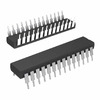 ATMEGA88V-10PJMicrochip TechnologyIC MCU 8BIT 8KB FLASH 28DIP
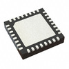 ATMEGA88V-10MIMicrochip TechnologyIC MCU 8BIT 8KB FLASH 32VQFN
 ATMEGA88PV-10MUAtmelIC MCU 8BIT 8KB FLASH 32VQFN
 ATMEGA88VAtmel (Microchip Technology)
 ATMEGA88V-10MURMicrochip


