ATTINY44-20MUR (1)
Manufacturer Part Number
ATTINY44-20MUR
Manufacturer
Microchip Technology
Introduction
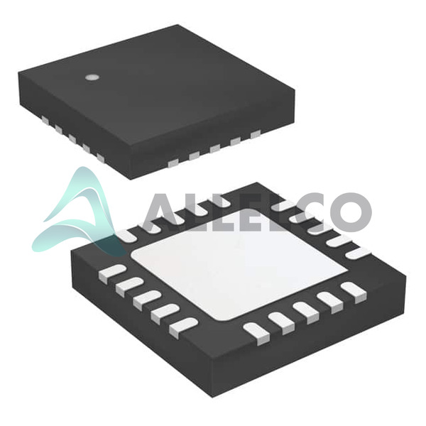
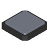
The ATTINY44-20MUR is an AVR® ATtiny series 8-bit microcontroller designed for high-performance, low-power computing needs, provided in a compact 20-QFN-EP surface mount package.
Product Features and Performance
Core Processor: AVR 8-Bit
Speed: 20 MHz
Connectivity: USI (Universal Serial Interface)
Peripherals: Brown-out Detect/Reset, Power-On Reset, Pulse Width Modulation, Watchdog Timer
Number of I/O: 12
Program Memory: 4KB FLASH
EEPROM: 256 x 8
RAM: 256 x 8
Data Converters: 8-channel 10-bit Analog-to-Digital converter
Oscillator: Internal
Operating Temperature Range: -40°C ~ 85°C
Product Advantages
Integrated features to handle system-level brownouts and power resets enhancing overall system robustness.
Wide voltage supply range (2.7V to 5.5V) makes it suitable for a variety of applications.
Compact footprint and surface mount package for space-sensitive applications.
Key Technical Parameters
Flash Memory: 4KB (2K x 16)
RAM: 256 Bytes
EEPROM: 256 Bytes
10-bit ADC with 8 channels
PWM Channels
Watchdog Timer
Quality and Safety Features
Brown-out Detect/Reset ensures proper operation under low voltage conditions.
Operates stably within a temperature range of -40°C to 85°C.
Compatibility
Compatible with USI communication for connectivity with other digital systems.
Application Areas
Consumer Electronics
Industrial Control
Automotive Systems
IoT Devices
Product Lifecycle
Currently status: Active
Not nearing discontinuation and expected to have continued availability along with potential upgrades.
Several Key Reasons to Choose This Product
High-speed 20 MHz performance for timely computing and processing.
Extensive memory and peripherals reduce additional component needs.
Robust data converters for accurate analog to digital data handling.
Reliable operation across a wide range of environmental conditions.
Surface-mount technology facilitating smaller, compact designs.

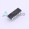 ATTINY44-20PUMicrochip TechnologyIC MCU 8BIT 4KB FLASH 14DIP
 ATTINY441-MMHMicrochip TechnologyIC MCU 8BIT 4KB FLASH 20VQFN
 ATTINY44-20SSUMicrochip TechnologyIC MCU 8BIT 4KB FLASH 14SOIC
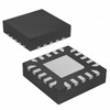 ATTINY441-MMHRMicrochip TechnologyIC MCU 8BIT 4KB FLASH 20VQFN
 ATTINY44-15SSZAtmelIC MCU 8BIT 4KB FLASH 14SOIC
 ATTINY43U-SUMicrochip TechnologyIC MCU 8BIT 4KB FLASH 20SOIC
 ATTINY441-MMHAtmelIC MCU 8BIT 4KB FLASH 20VQFN
 ATTINY44-15SSZMicrochip TechnologyIC MCU 8BIT 4KB FLASH 14SOIC
 ATTINY441-16SSUAtmel (Microchip Technology)


