View All

Please refer to the English Version as our Official Version.Return

Europe
France(Français) Germany(Deutsch) Italy(Italia) Russian(русский) Poland(polski) Czech(Čeština) Luxembourg(Lëtzebuergesch) Netherlands(Nederland) Iceland(íslenska) Hungarian(Magyarország) Spain(español) Portugal(Português) Turkey(Türk dili) Bulgaria(Български език) Ukraine(Україна) Greece(Ελλάδα) Israel(עִבְרִית) Sweden(Svenska) Finland(Svenska) Finland(Suomi) Romania(românesc) Moldova(românesc) Slovakia(Slovenská) Denmark(Dansk) Slovenia(Slovenija) Slovenia(Hrvatska) Croatia(Hrvatska) Serbia(Hrvatska) Montenegro(Hrvatska) Bosnia and Herzegovina(Hrvatska) Lithuania(lietuvių) Spain(Português) Switzerland(Deutsch) United Kingdom(English)
Asia/Pacific
Japan(日本語) Korea(한국의) Thailand(ภาษาไทย) Malaysia(Melayu) Singapore(Melayu) Vietnam(Tiếng Việt) Philippines(Pilipino)
Africa, India and Middle East
United Arab Emirates(العربية) Iran(فارسی) Tajikistan(فارسی) India(हिंदी) Madagascar(malaɡasʲ)
South America / Oceania
New Zealand(Maori) Brazil(Português) Angola(Português) Mozambique(Português)
North America
United States(English) Canada(English) Haiti(Ayiti) Mexico(español)
HomeProductsCircuit ProtectionTVS - DiodesMSMLJ60CAE3
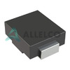
MSMLJ60CAE3 Image
Image may be representation.
See specifications for product details.
EXPRESS OPTION
Payment method

MSMLJ60CAE3 - Microchip Technology

Manufacturer Part Number
MSMLJ60CAE3
Manufacturer
Microchip Technology
Allelco Part Number
98D-MSMLJ60CAE3
Warranty
1 Year Allelco Warranty - Find out more
Stock Status:
34,531 pcs available, New & Original
Parts Description
TVS DIODE 60VWM 96.8VC DO214AB
Package
DO-214AB
Data sheet
MSMLJ60CAE3.pdf

PCN Assembly/Origin

2.73KHz.pdf
RoHs Status
 
Our certification
In stock: 34531
  • Unit Price: $2.58
  • Subtotal: $0.00

Want a better price?
Add to Cart and Submit RFQ now, we'll contact you immediately.

Quantity Unit Price Ext. Price
1+ $2.58 $2.58
The above prices does not include taxes and freight rates, which will be calculated on the order pages.

Specifications

MSMLJ60CAE3 Tech Specifications
Microchip Technology - MSMLJ60CAE3 technical specifications, attributes, parameters and parts with similar specifications to Microchip Technology - MSMLJ60CAE3

Product Attribute Attribute Value
Manufacturer Microchip Technology
Voltage - Reverse Standoff (Typ) 60V
Voltage - Clamping (Max) @ Ipp 96.8V
Voltage - Breakdown (Min) 66.7V
Type Zener
Supplier Device Package DO-214AB
Series Military, MIL-PRF-19500
Power Line Protection No
Power - Peak Pulse 3000W (3kW)
Product Attribute Attribute Value
Package / Case DO-214AB, SMC
Package Bulk
Operating Temperature -65°C ~ 150°C (TJ)
Mounting Type Surface Mount
Current - Peak Pulse (10/1000µs) 31A
Capacitance @ Frequency -
Bidirectional Channels 1
Base Product Number SMLJ60
Applications General Purpose

Environmental & Export Classifications

ATTRIBUTE DESCRIPTION
RoHs Status RoHS non-compliant
Moisture Sensitivity Level (MSL) 1 (Unlimited)
REACH Status REACH Unaffected
ECCN EAR99
HTSUS 8541.10.0080

Frequently Asked Questions(FAQ)

What are the key electrical characteristics of the MSMLJ60CAE3 TVS diode that influence its selection for transient protection in 60V power systems?
The MSMLJ60CAE3 is engineered to protect 60V nominal systems with a reverse standoff voltage of 60V and a minimum breakdown voltage of 66.7V, ensuring it remains inactive under normal operating conditions while providing reliable overvoltage detection. When triggered by a transient event, such as an ESD pulse or inductive kickback, it clamps the voltage to a maximum of 96.8V at a peak current of 31A, which helps limit stress on downstream components. With a peak pulse power rating of 3kW, this device can absorb substantial energy without degradation, making it suitable for applications where high-energy transients may occur. These parameters collectively define its suitability for general-purpose protection in industrial, automotive, or telecommunications environments where voltage spikes must be controlled within safe limits.
How does the clamping performance of the MSMLJ60CAE3 compare to other SMLJ series devices when subjected to high-current surge events?
Compared to other SMLJ series variants like the MSMLJ58CAE3 or MSMLJ65CAE3, the MSMLJ60CAE3 offers a balanced clamping response at 96.8V for a 31A peak pulse current, which is typical for its 60V working range. Devices with lower standoff voltages, such as the SMLJ58, exhibit slightly lower clamping thresholds but are optimized for systems operating closer to 58V. Conversely, higher-voltage members like the SMLJ65 have a higher breakdown threshold and correspondingly elevated clamping voltage, which may result in greater stress on protected circuitry if not matched to system requirements. The MSMLJ60CAE3 thus represents a mid-range option where transient energy absorption and final clamped voltage are carefully aligned for 60V rails, offering design engineers a predictable trade-off between sensitivity and protection margin.
What thermal and mechanical considerations should be addressed when integrating the MSMLJ60CAE3 into a high-reliability military-grade circuit design?
Given its military qualification (MIL-PRF-19500) and wide operating junction temperature range from -65°C to 150°C, the MSMLJ60CAE3 is inherently suited for extreme environments. However, during pulsed operation—such as when absorbing a 3kW transient—the internal junction temperature must remain within safe limits to avoid thermal runaway or failure. Proper PCB layout is essential: the DO-214AB package has a small footprint but limited thermal mass, so adequate copper area and via stitching beneath the pad improve heat dissipation. Additionally, since it is surface-mount, solder joint integrity under thermal cycling must be verified, especially in vibration-prone applications. Designers should also consider derating the peak pulse power in continuous high-frequency transient scenarios to maintain long-term reliability.
Can the MSMLJ60CAE3 be used for bidirectional protection in AC-coupled or differential signaling lines?
No, the MSMLJ60CAE3 is a unidirectional Zener-type TVS diode with a single bidirectional channel, but it functions primarily as a Zener clamp in one direction and avalanche in the reverse. While it provides some level of reverse protection, it is not optimized for true bidirectional symmetrical surge suppression required in AC signal lines or differential pairs. For such applications, a dedicated bidirectional TVS array with symmetric clamping characteristics—such as a pair of back-to-back Zeners or a specialized dual-diode structure—is typically preferred. The MSMLJ60CAE3 may still offer incidental protection in certain DC-biased systems, but its asymmetrical response makes it less ideal for balanced communication interfaces like RS-485 or CAN bus where both polarities must be handled uniformly.
How does the capacitance profile of the MSMLJ60CAE3 influence its use in high-speed digital communication interfaces?
Although the datasheet does not specify capacitance, the physical construction of the MSMLJ60CAE3 suggests moderate junction capacitance, likely in the low hundreds of picofarads. This can induce signal distortion or attenuation in high-speed lines such as USB, Ethernet (e.g., 10/100/1000BASE-T), or LVDS, where impedance matching and minimal loading are critical. At data rates above 1 Gbps, even small parasitic capacitance can cause reflections or eye diagram degradation. Therefore, while the MSMLJ60CAE3 may be acceptable for slower control signals or power rail protection, it should be avoided in direct parallel with high-speed data traces unless accompanied by filtering or isolation techniques to mitigate capacitive coupling effects.
What are the implications of the RoHS non-compliance status for the MSMLJ60CAE3 in modern supply chain and regulatory contexts?
The MSMLJ60CAE3 is marked as RoHS non-compliant, meaning it contains restricted substances such as lead in quantities exceeding current EU directives. This restricts its use in consumer electronics sold in Europe unless an exemption applies. In defense, aerospace, or legacy industrial systems where RoHS exemptions are permitted, this limitation may be acceptable. However, procurement teams must verify end-use compliance and consider alternative components like the SMF-series (which are RoHS-compliant) if environmental regulations apply. Suppliers may offer custom packaging or documentation to support restricted-use applications, but design integration should account for potential rework risks during assembly if transitioning from RoHS-compliant platforms.
Is the MSMLJ60CAE3 suitable for repeated transient events, and how does its endurance compare to standard commercial-grade TVS diodes?
Yes, the MSMLJ60CAE3 is rated for multiple surge events under specified conditions (typically 1,000 pulses of 10/1000µs waveform per MIL-STD-750). Its military-grade qualification implies enhanced robustness compared to most commercial TVS diodes, which often lack rigorous life-cycle testing. However, each transient dissipates significant power—3kW for a full 10/1000µs pulse—and repeated exposure without sufficient recovery time can degrade performance due to cumulative thermal stress. In practice, most designs rely on infrequent transients, so longevity is rarely an issue. Still, in harsh environments with frequent surges (e.g., motor-driven systems), monitoring for shift in clamping voltage or increased leakage becomes prudent. The component’s MSL 1 rating also ensures no moisture sensitivity concerns during storage, supporting consistent performance over time.
How should the MSMLJ60CAE3 be positioned relative to protected loads to maximize effectiveness against fast-rising transients?
To ensure optimal protection, the MSMLJ60CAE3 should be placed as close as possible to the point of entry of the transient—typically near connectors, switches, or cable shields—where high-impedance paths allow voltage buildup. A short ground return path minimizes inductance, reducing the effective clamping voltage during fast rise times (e.g., 8/20µs or 10/1000µs waveforms). Using wide traces and minimizing loop area between the diode terminals and the load improves transient response by lowering parasitic inductance. Additionally, placing bypass capacitors near the protected node helps shunt high-frequency noise before it reaches the TVS, allowing the MSMLJ60CAE3 to focus on high-energy pulses rather than filtering broadband interference.
Can the MSMLJ60CAE3 replace a fuse or PTC thermistor in overcurrent protection schemes for 60V DC power rails?
No, the MSMLJ60CAE3 is designed exclusively for voltage transient suppression and does not respond to sustained overcurrent conditions. It cannot function as a resettable fuse or provide primary overcurrent protection. Unlike PTCs or fuses, which increase resistance or break the circuit during excessive current flow, the MSMLJ60CAE3 remains conductive once triggered and only limits voltage spikes. Therefore, it complements but does not substitute for current-limiting elements. In robust designs, the MSMLJ60CAE3 protects against fast transients while separate overcurrent protection mechanisms handle slow faults, ensuring comprehensive safety across different fault types and durations.

Parts with Similar Specifications

The three parts on the right have similar specifications to Microchip Technology MSMLJ60CAE3

Product Attribute MSMLJ60CAE3/TR MSMLJ64CAE3 MSMLJ60AE3/TR MSMLJ6.5CAE3
Part Number MSMLJ60CAE3/TR MSMLJ64CAE3 MSMLJ60AE3/TR MSMLJ6.5CAE3
Manufacturer Microchip Technology Microchip Technology Microchip Technology Microchip Technology
Power - Peak Pulse - - - -
Series - - - -
Capacitance @ Frequency - - - -
Voltage - Breakdown (Min) - - - -
Power Line Protection - - - -
Base Product Number - DAC34H84 MAX500 ADS62P42
Voltage - Clamping (Max) @ Ipp - - - -
Operating Temperature - -40°C ~ 85°C 0°C ~ 70°C -40°C ~ 85°C
Type - - - -
Supplier Device Package - 196-NFBGA (12x12) 16-PDIP 64-VQFN (9x9)
Package - Tape & Reel (TR) Tube Tape & Reel (TR)
Mounting Type - Surface Mount Through Hole Surface Mount
Applications - - - -
Voltage - Reverse Standoff (Typ) - - - -
Package / Case - 196-LFBGA 16-DIP (0.300', 7.62mm) 64-VFQFN Exposed Pad
Current - Peak Pulse (10/1000µs) - - - -
Bidirectional Channels - - - -

MSMLJ60CAE3 Datasheet PDF

Download MSMLJ60CAE3 pdf datasheets and Microchip Technology documentation for MSMLJ60CAE3 - Microchip Technology.

PCN Assembly/Origin
2.73KHz.pdf
HTML Datasheet
MSMLx5.0A - MSMLx170CAe3.pdf

Customer Reviews

Evaluation: 10 Articles

  • Embe***dMotion
    Aug 5, 2026

    Purchased this DSP controller for a motor control application. Stable processing performance and very good response under varying loads.

  • FPGA***dio
    Jul 30, 2026

    This FPGA handled our logic design without any surprises. Configuration completed quickly and timing met the project requirements.

  • Nord***mbedded
    Jul 20, 2026

    Reliable FPGA with predictable behavior. Configuration and testing went smoothly, making development faster than expected.

  • Arch***ct
    Jul 15, 2026

    Used this device in a communication signal processing board. Stable timing and no unexpected issues during implementation.

  • FPGA***lorer88
    Jul 7, 2026

    The FPGA works properly and all functions operate as expected. Documentation required some additional research, but overall it is a usable device for smaller signal processing projects.

  • Nath***oleman
    Jun 29, 2026

    Used this sensor component in an industrial automation setup. Detection accuracy was consistent and installation was straightforward.

  • Emil***rperTech
    Jun 23, 2026

    Works exactly as described. I used it as a USB-to-SPI bridge in a small MCU development project and communication was stable from the first setup.

  • Liam***terTech
    Jun 15, 2026

    Used this CPLD in a logic control project. Programming was straightforward and signal timing matched the design requirements.

  • Nath***rooks
    Jun 11, 2026

    Installed this power component in a converter board. Output remained stable under different load conditions and thermal performance was better than expected.

  • Dani***alkerTech
    Jun 1, 2026

    Product works, but setup took more effort than expected. Once configured the MCU ran reliably, although documentation support felt older compared with newer platforms. Fine for maintenance projects.

Write a Review

Your Email address will not be published.

Shipment

Delivery Time

In-stock items can be shipped within 24 hours. Some parts will be arranged for delivery within 1-2 days from the date all items arrive at our warehouse. And Allelco ships order once a day at about 17:00, except Sunday. Once the goods are shipped, the estimated delivery time depends on the shipping methods and Delivery destination. The table below shows are the logistic time for some common countries.

Delivery Cost

  1. Use your express account for shipment if you have one.
  2. Use our account for the shipment. Refer to the table below for the approximate charges.
(Different time frame / countries / package size has different price.)

Delivery Method

  1. Global Common Shipment by DHL / UPS / FedEx / TNT / EMS / SF we support.
  2. Others more shipping ways, please get in touch with your customer manager.

Common Countries Logistic Time Reference
Region Country Logistic Time(Day)
America United States 5
Brazil 7
Europe Germany 5
United Kingdom 4
Italy 5
Oceania Australia 6
New Zealand 5
Asia India 4
Japan 4
Middle East Israel 6
DHL & FedEx Shipment Charges Reference
Shipment charges(KG) Reference DHL(USD$)
0.00kg-1.00kg USD$30.00 - USD$60.00
1.00kg-2.00kg USD$40.00 - USD$80.00
2.00kg-3.00kg USD$50.00 - USD$100.00
Note:
The above table is for reference only. There may have some data bias for the uncontrollable factors.
Contact us if you have any questions.
  • QC (Quality Warranty)
  • Payment Support
  • Packaging
  • Certifications & Memberships

QC (Quality Warranty)

Allelco is committed to exceeding customer expectations through customer service excellence, order accuracy, and on-time delivery.
This is achieved through our commitment to the continual improvement of our processes, services, and products.


Strict quality inspection builds a solid foundation for electronic component quality.
  1. Visual inspection
  2. Performance testing and reliability verification
  3. Standardized full-process testing
  4. Precise control of every parameter
We eliminate defective components and ensure the stable operation of electronic devices through professional quality standards.

Payment Support

The payment method can be chosen from the methods shown below: Wire Transfer (T/T, Bank Transfer), Western Union, Credit card, PayPal.
  • HKBea
  • Paypal
  • MasterCard
  • Western-Union
  • VISA
Stable Delivery, Sincere Partnership — Your Faithful Supply Chain Partner
  • Efficient Supply Management
  • Cost-Saving Procurement
  • Fast Sourcing & Delivery
Contact us if you have any questions.
Packaging

Electrostatic Discharge Protection and Handling

All electrostatic-sensitive components are handled in accordance with electrostatic discharge control procedures. The products are hermetically sealed in anti-static safe packaging to prevent electrostatic damage. Appropriate labeling is also applied for identification and traceability. This ensures product integrity during storage, handling and transportation.


ESD

Certifications & Memberships

Third-party certified, strict quality control. Our certification
  • ISO 9001: 2015
  • ISO 13485: 2016
  • ISO 14001: 2015
  • ISO 28000: 2007
  • ISO 45001: 2018
  • GB/T 27922-2011
  • SMTA
  • IPC
  • ESD
  • PSMA
MSMLJ60CAE3 Image

MSMLJ60CAE3

Microchip Technology
98D-MSMLJ60CAE3

Want a better price? Add to Cart and Submit RFQ now, we'll contact you immediately.

0 RFQ
Shopping cart (0 Items)
It is empty.
Compare List (0 Items)
It is empty.
Feedback

Your feedback matters! At Allelco, we value the user experience and strive to improve it constantly.
Please share your comments with us via our feedback form, and we'll respond promptly.
Thank you for choosing Allelco.

Subject
E-mail
Comments
Captcha
Drag or click to upload file
Upload File
types: .xls, .xlsx, .doc, .docx, .jpg, .png and .pdf.
Max file size: 10MB