View All

Please refer to the English Version as our Official Version.Return

Europe
France(Français) Germany(Deutsch) Italy(Italia) Russian(русский) Poland(polski) Czech(Čeština) Luxembourg(Lëtzebuergesch) Netherlands(Nederland) Iceland(íslenska) Hungarian(Magyarország) Spain(español) Portugal(Português) Turkey(Türk dili) Bulgaria(Български език) Ukraine(Україна) Greece(Ελλάδα) Israel(עִבְרִית) Sweden(Svenska) Finland(Svenska) Finland(Suomi) Romania(românesc) Moldova(românesc) Slovakia(Slovenská) Denmark(Dansk) Slovenia(Slovenija) Slovenia(Hrvatska) Croatia(Hrvatska) Serbia(Hrvatska) Montenegro(Hrvatska) Bosnia and Herzegovina(Hrvatska) Lithuania(lietuvių) Spain(Português) Switzerland(Deutsch) United Kingdom(English)
Asia/Pacific
Japan(日本語) Korea(한국의) Thailand(ภาษาไทย) Malaysia(Melayu) Singapore(Melayu) Vietnam(Tiếng Việt) Philippines(Pilipino)
Africa, India and Middle East
United Arab Emirates(العربية) Iran(فارسی) Tajikistan(فارسی) India(हिंदी) Madagascar(malaɡasʲ)
South America / Oceania
New Zealand(Maori) Brazil(Português) Angola(Português) Mozambique(Português)
North America
United States(English) Canada(English) Haiti(Ayiti) Mexico(español)
HomeProductsIntegrated Circuits (ICs)Embedded - MicrocontrollersPIC16F874-20/PT
PIC16F874-20/PT Image
Image may be representation.
See specifications for product details.
EXPRESS OPTION
Payment method

PIC16F874-20/PT - Microchip Technology

Manufacturer Part Number
PIC16F874-20/PT
Manufacturer
Microchip Technology
Allelco Part Number
32D-PIC16F874-20/PT
Warranty
1 Year Allelco Warranty - Find out more
Stock Status:
15,160 pcs available, New & Original
Parts Description
IC MCU 8BIT 7KB FLASH 44TQFP
Package
44-TQFP (10x10)
Data sheet
PIC16F874-20/PT.pdf
RoHs Status
ROHS3 Compliant
Our certification
In stock: 15160

Required fields are indicated by an asterisk (*)
Please send RFQ, we will respond immediately.

Quantity

Specifications

PIC16F874-20/PT Tech Specifications
Microchip Technology - PIC16F874-20/PT technical specifications, attributes, parameters and parts with similar specifications to Microchip Technology - PIC16F874-20/PT

Product Attribute Attribute Value
Manufacturer Microchip Technology
Voltage - Supply (Vcc/Vdd) 4V ~ 5.5V
Supplier Device Package 44-TQFP (10x10)
Speed 20MHz
Series PIC® 16F
RAM Size 192 x 8
Program Memory Type FLASH
Program Memory Size 7KB (4K x 14)
Peripherals Brown-out Detect/Reset, POR, PWM, WDT
Package / Case 44-TQFP
Package Tray
Product Attribute Attribute Value
Oscillator Type External
Operating Temperature 0°C ~ 70°C (TA)
Number of I/O 33
Mounting Type Surface Mount
EEPROM Size 128 x 8
Data Converters A/D 8x10b
Core Size 8-Bit
Core Processor PIC
Connectivity I²C, SPI, UART/USART
Base Product Number PIC16F874

Environmental & Export Classifications

ATTRIBUTE DESCRIPTION
RoHs Status ROHS3 Compliant
Moisture Sensitivity Level (MSL) 3 (168 Hours)
REACH Status REACH Unaffected
ECCN EAR99
HTSUS 8542.31.0001

Parts Introduction

PIC16F874-20/PT Image
PIC16F874-20/PT (1)

Manufacturer Part Number

PIC16F874-20/PT

Manufacturer

Microchip Technology

Introduction

The PIC16F874-20/PT is a powerful 8-bit microcontroller from Microchip Technology's PIC® 16F series, designed for embedded applications.

Product Features and Performance

Core Processor: PIC

Core Size: 8-Bit

Speed: 20MHz

Connectivity: I2C, SPI, UART/USART

Peripherals: Brown-out Detect/Reset, Power-on Reset, PWM, Watchdog Timer

Number of I/O: 33

Program Memory Size: 7KB (4K x 14)

Program Memory Type: FLASH

EEPROM Size: 128 x 8

RAM Size: 192 x 8

Voltage Supply (Vcc/Vdd): 4V to 5.5V

Data Converters: A/D 8x10b

Oscillator Type: External

Operating Temperature: 0°C to 70°C

Product Advantages

Robust I/O capabilities with 33 pins

Efficient power management with brown-out detect and power-on reset features

Flexible connectivity options including I2C, SPI, and UART/USART

Suitable for real-time applications due to PWM functionality and high-speed operation at 20MHz

Key Technical Parameters

Core Size: 8-Bit

Speed: 20MHz

EEPROM Size: 128 x 8

Operating Voltage: 4V to 5.5V

A/D Converters: 8 channels, 10-bit resolution

Quality and Safety Features

Watchdog Timer for system reliability

Brown-out Detect/Reset for stable operation under varying power conditions

Compatibility

Compatible with other devices in the PIC® 16F series

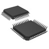
Surface Mount 44-TQFP packaging aligns with standard assembly techniques

Application Areas

Automotive systems

Industrial automation

Consumer electronics

Embedded control systems

Product Lifecycle

Product status: Obsolete

Customers should consider upgrades or replacements due to discontinuation

Several Key Reasons to Choose This Product

High reliability with a wide operating temperature range and advanced safety features

Extensive connectivity options cater to modern communication needs

Broad application suitability enhances design flexibility

Obsolescence offers potential cost benefits for end-of-life projects
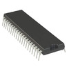
Frequently Asked Questions(FAQ)

How does the PIC16F874-20/PT perform in low-voltage applications, and what design considerations are necessary when operating near its minimum supply voltage of 4V?
The PIC16F874-20/PT is designed to operate reliably within a supply range of 4V to 5.5V, making it suitable for battery-powered or energy-constrained embedded systems. However, performance characteristics such as instruction execution timing, ADC accuracy, and peripheral functionality—including I2C and SPI communication—can degrade as Vcc approaches 4V due to reduced noise margins and slower internal logic transitions. Engineers should ensure stable power delivery, implement adequate decoupling capacitance, and verify oscillator stability under low-voltage conditions. Additionally, the brown-out reset (BOR) feature becomes critical near this threshold to prevent unintended resets during voltage dips.
What are the key differences between the PIC16F874-20/PT and a typical 8-bit microcontroller in terms of memory architecture and peripheral integration?
Unlike many generic 8-bit MCUs, the PIC16F874-20/PT features a Harvard architecture with separate program and data buses, enhancing code throughput by allowing simultaneous instruction fetch and data access. It integrates 7KB of Flash program memory, 192 bytes of RAM, and 128 bytes of EEPROM, which supports in-field updates without external storage. The inclusion of multiple communication interfaces—I2C, SPI, and UART/USART—along with analog peripherals like an 8-channel 10-bit ADC, enables complex sensor interfacing and system coordination within a compact pin count of 33 I/O lines.
When selecting between the PIC16F874-20/PT and similar devices like the PIC16F884-I/PT, what factors should influence the decision regarding flash memory size and real-time performance?
While both share core architectural similarities, the PIC16F884-I/PT offers larger program memory (up to 14KB) compared to the 7KB of the PIC16F874-20/PT, making it more suitable for firmware-heavy applications requiring extensive libraries or protocol stacks. However, the PIC16F874-20/PT maintains competitive performance at 20MHz, which may be sufficient for moderate control tasks. Designers should evaluate whether additional code space justifies potential trade-offs in package compatibility or power characteristics, especially if legacy hardware constraints exist.
Can the PIC16F874-20/PT be used in industrial environments, and how do its operating temperature and packaging contribute to reliability?
Although specified for commercial operation from 0°C to 70°C, the PIC16F874-20/PT’s 44-TQFP (10x10) surface-mount package provides good thermal dissipation and mechanical stability, supporting use in controlled industrial settings. However, extended exposure beyond 70°C risks degraded performance and accelerated aging. For harsh environments, external thermal management or component derating is advisable. The Moisture Sensitivity Level 3 designation also implies careful handling during assembly to avoid popcorning during reflow soldering.
What impact does using an external oscillator have on the PIC16F874-20/PT compared to internal clock sources, and how does this affect timing-sensitive designs?
The PIC16F874-20/PT relies on an external oscillator for its maximum rated speed of 20MHz, ensuring precise and stable timing for applications such as motor control, communication protocols, or sampled-data systems. Using an external crystal or ceramic resonator improves frequency accuracy over internal RC oscillators but adds PCB complexity and cost. In contrast, internal clocks simplify layout but reduce jitter tolerance and long-term drift. Timing-critical designs benefit from external oscillators paired with proper load capacitors and trace routing to maintain signal integrity.
How does the 10-bit ADC in the PIC16F874-20/PT handle input signal conditioning, and what limitations should designers anticipate?
The integrated 8-channel 10-bit ADC provides sufficient resolution for most analog sensing applications—such as temperature monitoring or voltage scaling—with a theoretical dynamic range of approximately 0.98mV per LSB at full scale. However, its performance is sensitive to supply noise, reference stability, and sampling time configuration. Without external buffering or filtering, high-impedance sources or fast-changing signals can introduce errors. Designers must account for these factors through proper analog front-end design and software calibration to meet application-specific accuracy requirements.
Is the PIC16F874-20/PT suitable for safety-critical applications, and what built-in features support system robustness?
While not certified for functional safety standards like ISO 26262 or IEC 61508, the PIC16F874-20/PT includes several features that enhance reliability in non-certified critical systems: a watchdog timer (WDT), power-on reset (POR), brown-out detect (BOR), and programmable voltage thresholds. These mechanisms help recover from software hangs, power anomalies, and undervoltage conditions, reducing risk of failure modes. Nevertheless, additional redundancy, fault logging, or external supervision circuits would be required for true safety-critical deployment.
What are the implications of the PIC16F874-20/PT’s 33 I/O pins on PCB layout and signal integrity, particularly when driving capacitive loads or long traces?
With 33 bidirectional I/O pins, the PIC16F874-20/PT offers flexibility but demands careful attention to drive strength, slew rates, and impedance matching. Driving capacitive loads directly—such as unterminated cables or large pull-up networks—can increase switching current and degrade timing margins. Long traces exacerbate ringing and crosstalk, especially on high-speed lines like SPI or UART. Layout practices including series termination, ground planes, and minimized stub lengths are essential to maintain signal fidelity and meet timing budgets at 20MHz operation.
How does the flash memory write endurance of the PIC16F874-20/PT compare to modern microcontrollers, and what affects its longevity in frequent update scenarios?
The PIC16F874-20/PT’s Flash memory typically supports around 10,000 erase/write cycles per sector, which is lower than contemporary devices with wear-leveling algorithms and higher endurance ratings. Frequent firmware updates or EEPROM emulation via Flash will eventually lead to wear-out. To extend lifespan, designers should minimize write operations, use only designated EEPROM-like blocks, and implement cycle-counting safeguards. Alternatives like external FRAM may be preferable for high-write-rate applications.
What role does the UART/USART module play in the PIC16F874-20/PT, and how should baud rate accuracy be ensured in serial communication?
The UART/USART peripheral enables asynchronous serial communication with standard protocols such as RS-232 or LIN, facilitating host interface or debug output. Baud rate accuracy depends on clock source precision; at 20MHz with a standard baud generator setup, achievable rates like 115200 bps require careful prescaler selection to stay within ±2% error tolerance. Mismatched rates cause framing errors and data loss. Designers should validate baud rates across worst-case crystal tolerances and consider using synchronous modes or hardware flow control for robust links.
How does the choice of programming interface affect development workflow when working with the PIC16F874-20/PT?
The PIC16F874-20/PT supports In-Circuit Serial Programming (ICSP) via two dedicated pins, enabling code updates without removing the device from the target board. This accelerates debugging and production flashing but requires minimal hardware overhead. However, ICSP access consumes limited I/O resources and must be protected against unauthorized reprogramming. Development tools like MPLAB X IDE integrate seamlessly with Microchip programmers, streamlining firmware deployment while maintaining security through configuration bits.
What environmental and regulatory considerations apply to the PIC16F874-20/PT, and how do RoHS, REACH, and export classifications impact global design adoption?
The PIC16F874-20/PT complies with RoHS3 directives, meaning it contains no restricted substances above legal thresholds, supporting sustainable design initiatives. Its REACH status indicates no SVHCs (Substances of Very High Concern) declared, simplifying compliance documentation. Export-wise, it falls under ECCN EAR99 and HTSUS 8542.31.0001, indicating minimal trade restrictions and ease of international procurement. These attributes facilitate global manufacturing and distribution without unexpected regulatory hurdles.
How does the PIC16F874-20/PT’s PWM module support motor control or LED dimming applications, and what are its limitations?
The device includes up to five CCP (Capture/Compare/PWM) modules capable of generating adjustable-duty-cycle waveforms for PWM outputs. With a 20MHz system clock, the maximum PWM frequency is approximately 5kHz when using 8-bit resolution, suitable for low-to-medium-speed motor drives or LED brightness control. However, finer resolution or higher frequencies require prescaler adjustments or external circuitry. Fixed-frequency operation limits flexibility in audio or high-precision timing contexts, where variable-frequency PWM may be needed.
What are the thermal implications of operating the PIC16F874-20/PT continuously at 20MHz in a compact enclosure?
At 20MHz, the PIC16F874-20/PT consumes typical active current of around 2–3mA per MHz under nominal conditions, translating to ~40–60mA at full speed. In a 44-pin TQFP package without heatsinking, sustained high CPU utilization generates heat that may raise junction temperature above ambient. While well within absolute maximum ratings, prolonged operation near upper temperature limits accelerates electromigration and reduces reliability. Adequate airflow or conservative clock gating improves thermal margins in sealed environments.
How does the EEPROM size of the PIC16F874-20/PT compare to other 8-bit PIC devices, and when would external non-volatile storage be preferred?
With 128 x 8 bytes of internal EEPROM, the PIC16F874-20/PT provides modest persistent storage for calibration data, user settings, or small logs. This suffices for basic parameter retention but becomes restrictive for large datasets or frequent writes. Compared to newer PICs with larger EEPROM or FRAM, it lacks endurance for high-volume logging. In such cases, external I²C-based EEPROMs or SPI Flash offer greater capacity and cycle life, albeit with added component count and latency.
What precautions are necessary when migrating existing designs from earlier PIC16F-series devices to the PIC16F874-20/PT?
Although based on the same core architecture, the PIC16F874-20/PT introduces updated register mappings, enhanced peripherals, and stricter timing constraints. Code originally targeting PIC16F87X variants may require updates to interrupt vector assignments, SFR accesses, or clock configuration routines. Additionally, differences in oscillator startup times, BOR thresholds, or I/O mapping necessitate thorough testing under real-world conditions. Maintaining version-controlled firmware branches and validating timing behavior post-migration minimizes risk of silent failures.
How does the PIC16F874-20/PT support low-power modes, and what trade-offs exist between wake-up latency and energy savings?
The device offers sleep mode, where most clocks stop except the watchdog timer and interrupt sources, reducing current consumption to under 1µA. However, waking from sleep incurs latency—typically tens to hundreds of microseconds—due to oscillator restart and context restoration. Applications requiring rapid response (e.g., remote controls) may prefer reduced sleep time over ultra-low quiescent current. Designers must balance duty cycling, event-driven operation, and acceptable wake-up delay to optimize battery life without compromising user experience.
Are there known limitations in using the PIC16F874-20/PT for CAN bus applications, and what alternatives should be considered?
The PIC16F874-20/PT lacks native CAN 2.0B controller functionality, which is essential for automotive or industrial networks requiring robust arbitration and error handling. While bit-banged implementations are theoretically possible using GPIO and precise timing, they are unreliable at high speeds (>125kbps) and lack hardware acceleration. For CAN-enabled designs, upgrading to PIC18 or PIC24 families with integrated CAN peripherals is strongly recommended to ensure compliance, determinism, and interoperability.

Parts with Similar Specifications

The three parts on the right have similar specifications to Microchip Technology PIC16F874-20/PT

Product Attribute PIC16F874-20I/PT PIC16F874-20/PQ PIC16F874-10E/PT PIC16F874-04I/PT
Part Number PIC16F874-20I/PT PIC16F874-20/PQ PIC16F874-10E/PT PIC16F874-04I/PT
Manufacturer Microchip Technology Microchip Technology Microchip Technology Microchip Technology
Mounting Type - Surface Mount Through Hole Surface Mount
Base Product Number - DAC34H84 MAX500 ADS62P42
Oscillator Type - - - -
Speed - - - -
Data Converters - - - -
Voltage - Supply (Vcc/Vdd) - - - -
Peripherals - - - -
Package - Tape & Reel (TR) Tube Tape & Reel (TR)
Core Size - - - -
EEPROM Size - - - -
Core Processor - - - -
Number of I/O - - - -
RAM Size - - - -
Package / Case - 196-LFBGA 16-DIP (0.300', 7.62mm) 64-VFQFN Exposed Pad
Series - - - -
Operating Temperature - -40°C ~ 85°C 0°C ~ 70°C -40°C ~ 85°C
Supplier Device Package - 196-NFBGA (12x12) 16-PDIP 64-VQFN (9x9)
Program Memory Size - - - -
Program Memory Type - - - -
Connectivity - - - -

PIC16F874-20/PT Datasheet PDF

Download PIC16F874-20/PT pdf datasheets and Microchip Technology documentation for PIC16F874-20/PT - Microchip Technology.

Datasheets
PIC16F87x Datasheet.pdf
PCN Obsolescence/ EOL
Cylindrical Battery Holders.pdf
PCN Packaging
Label and Packing Changes 23/Sep/2015.pdf MBB/Label Chgs 16/Nov/2018.pdf
HTML Datasheet
MPLAB® ICE2000 Spec.pdf PICmicro™ Reference Manual.pdf Tips N Tricks Guide.pdf
PCN Assembly/Origin
Qualification PDIP-28L/40 Revision 05/Sept/2013.pdf
PCN Design/Specification
TQFP-44L Palladium Coated Copper Wire 17/Dec/2013.pdf

Customer Reviews

Evaluation: 10 Articles

  • Nath***rooks
    Jun 11, 2026

    Installed this power component in a converter board. Output remained stable under different load conditions and thermal performance was better than expected.

  • Dani***alkerTech
    Jun 1, 2026

    Product works, but setup took more effort than expected. Once configured the MCU ran reliably, although documentation support felt older compared with newer platforms. Fine for maintenance projects.

  • Yuki***aka88
    May 26, 2026

    信号通信プロジェクトでこのRS-485トランシーバーを使用しました。設置は簡単で、長距離ケーブルでも通信は安定していました。消費電力も、以前使用していたものより低くなっています。

  • Stev***aker
    May 20, 2026

    Solid diode for power rectification. Works well in switching circuits.

  • Bran***Lewis
    May 11, 2026

    Compact FPGA with good performance. Suitable for basic signal processing tasks.

  • Oliv***arris
    May 7, 2026

    Reliable I/O expander. Works well in embedded control applications.

  • Jess***Jones
    Apr 17, 2026

    It offers good value for the price, and the specifications match the description. I’ve been using it for two days with no issues, and I’ll definitely buy it again if I need it in the future.

  • Mich***Smith
    Apr 17, 2026

    Shipping was on time, the component pins are neatly aligned, and I tested 10 of them with a multimeter—all readings were within the specified range. Highly recommended.

  • Aman***arris
    Apr 3, 2026

    It was great—the entire process, from placing the order to receiving the package, went very smoothly. The components were consistent, the price was fair, and I had a very pleasant shopping experience.

  • Mike***nch
    Apr 3, 2026

    Better than expected! The resistance and capacitance readings were spot-on, and it passed the test on the first try. The service was reliable, and the packaging was thoughtful—I highly recommend it.

Write a Review

Your Email address will not be published.

Shipment

Delivery Time

In-stock items can be shipped within 24 hours. Some parts will be arranged for delivery within 1-2 days from the date all items arrive at our warehouse. And Allelco ships order once a day at about 17:00, except Sunday. Once the goods are shipped, the estimated delivery time depends on the shipping methods and Delivery destination. The table below shows are the logistic time for some common countries.

Delivery Cost

  1. Use your express account for shipment if you have one.
  2. Use our account for the shipment. Refer to the table below for the approximate charges.
(Different time frame / countries / package size has different price.)

Delivery Method

  1. Global Common Shipment by DHL / UPS / FedEx / TNT / EMS / SF we support.
  2. Others more shipping ways, please get in touch with your customer manager.

Common Countries Logistic Time Reference
Region Country Logistic Time(Day)
America United States 5
Brazil 7
Europe Germany 5
United Kingdom 4
Italy 5
Oceania Australia 6
New Zealand 5
Asia India 4
Japan 4
Middle East Israel 6
DHL & FedEx Shipment Charges Reference
Shipment charges(KG) Reference DHL(USD$)
0.00kg-1.00kg USD$30.00 - USD$60.00
1.00kg-2.00kg USD$40.00 - USD$80.00
2.00kg-3.00kg USD$50.00 - USD$100.00
Note:
The above table is for reference only. There may have some data bias for the uncontrollable factors.
Contact us if you have any questions.
  • QC (Quality Warranty)
  • Payment Support
  • Packaging
  • Certifications & Memberships

QC (Quality Warranty)

Allelco is committed to exceeding customer expectations through customer service excellence, order accuracy, and on-time delivery.
This is achieved through our commitment to the continual improvement of our processes, services, and products.


Strict quality inspection builds a solid foundation for electronic component quality.
  1. Visual inspection
  2. Performance testing and reliability verification
  3. Standardized full-process testing
  4. Precise control of every parameter
We eliminate defective components and ensure the stable operation of electronic devices through professional quality standards.

Payment Support

The payment method can be chosen from the methods shown below: Wire Transfer (T/T, Bank Transfer), Western Union, Credit card, PayPal.
  • HKBea
  • Paypal
  • MasterCard
  • Western-Union
  • VISA
Stable Delivery, Sincere Partnership — Your Faithful Supply Chain Partner
  • Efficient Supply Management
  • Cost-Saving Procurement
  • Fast Sourcing & Delivery
Contact us if you have any questions.

Packaging

Electrostatic Discharge Protection and Handling

All electrostatic-sensitive components are handled in accordance with electrostatic discharge control procedures. The products are hermetically sealed in anti-static safe packaging to prevent electrostatic damage. Appropriate labeling is also applied for identification and traceability. This ensures product integrity during storage, handling and transportation.


ESD

Certifications & Memberships

Third-party certified, strict quality control. Our certification
  • ISO 9001: 2015
  • ISO 13485: 2016
  • ISO 14001: 2015
  • ISO 28000: 2007
  • ISO 45001: 2018
  • GB/T 27922-2011
  • SMTA
  • IPC
  • ESD
  • PSMA
PIC16F874-20/PT Image

PIC16F874-20/PT

Microchip Technology
32D-PIC16F874-20/PT

Want a better price? Add to Cart and Submit RFQ now, we'll contact you immediately.

0 RFQ
Shopping cart (0 Items)
It is empty.
Compare List (0 Items)
It is empty.
Feedback

Your feedback matters! At Allelco, we value the user experience and strive to improve it constantly.
Please share your comments with us via our feedback form, and we'll respond promptly.
Thank you for choosing Allelco.

Subject
E-mail
Comments
Captcha
Drag or click to upload file
Upload File
types: .xls, .xlsx, .doc, .docx, .jpg, .png and .pdf.
Max file size: 10MB