
Manufacturer Part Number
PIC12LC508AT-04/SM
Manufacturer
microchip-technology
Introduction
The PIC12LC508AT-04/SM is a low-power, 8-bit microcontroller from the PIC® 12C series. It features a PIC core, 768 bytes of OTP program memory, and 25 bytes of RAM. The device is designed for a wide range of embedded applications that require a compact and cost-effective solution.
Product Features and Performance
8-bit PIC core
4 MHz operating speed
768 bytes of OTP program memory
25 bytes of RAM
Power-on Reset (POR) and Watchdog Timer (WDT) peripherals
5 I/O pins
Operating voltage range of 2.5V to 5.5V
Operating temperature range of 0°C to 70°C
Product Advantages
Compact and cost-effective solution for embedded applications
Low-power consumption for battery-powered devices
Reliable operation with built-in POR and WDT peripherals
Flexible I/O options for interfacing with various sensors and peripherals
Key Reasons to Choose This Product
Proven Microchip technology for reliable performance
Suitable for a wide range of embedded applications
Easy to integrate into your design with the available development tools
Competitive pricing and availability
Quality and Safety Features
Robust design and manufacturing process
Compliance with industry standards for safety and reliability
Compatibility
Compatible with Microchip's extensive ecosystem of development tools and software
Application Areas
Automotive and industrial control systems
Home automation and security systems
Portable and battery-powered devices
Sensor and measurement applications
Product Lifecycle
The PIC12LC508AT-04/SM is an active product. There may be equivalent or alternative models available from Microchip. Please contact our website's sales team for more information on the current product status and availability of similar or updated models.
 PIC12LC508A-04/SMMicrochip TechnologyIC MCU 8BIT 768B OTP 8SOIJ
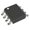 PIC12LC508AT-04/SNMicrochip TechnologyIC MCU 8BIT 768B OTP 8SOIC
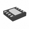 PIC12LC508AT-04I/MFMicrochip TechnologyIC MCU 8BIT 768B OTP 8DFN
 PIC12LC508A-04/PMicrochip TechnologyIC MCU 8BIT 768B OTP 8DIP
 PIC12LC508AT-04/SN197Micro Connectors, Inc.


