
Manufacturer Part Number
PIC16LF15325T-I/ST
Manufacturer
microchip-technology
Introduction
The PIC16LF15325T-I/ST is a powerful and versatile 8-bit microcontroller from Microchip Technology. It features a PIC core, 14KB of FLASH program memory, and a wide range of on-chip peripherals, making it suitable for a variety of embedded applications.
Product Features and Performance
8-bit PIC core with 32MHz operating speed
14KB FLASH program memory, 1KB RAM, and 224 bytes of EEPROM
Supports I2C, LIN bus, SPI, and UART/USART communication interfaces
Integrated peripherals including brown-out detect/reset, power-on reset (POR), PWM, and watchdog timer
12 I/O pins for flexible interfacing with external devices
11-channel 10-bit ADC and 1-channel 5-bit DAC for analog signal processing
Internal oscillator for easy system design
Product Advantages
Highly integrated and cost-effective 8-bit microcontroller solution
Low-power XLP technology for extended battery life in portable applications
Robust on-chip peripherals for versatile system integration
Broad operating voltage range of 1.8V to 3.6V
Key Reasons to Choose This Product
Proven reliability and performance of the PIC microcontroller architecture
Ease of use and extensive development tools and resources from Microchip
Ideal for a wide range of embedded applications, from home automation to industrial control
Long-term product availability and support from a leading semiconductor manufacturer
Quality and Safety Features
Industrial-grade operating temperature range of -40°C to 85°C
Robust package options, including surface-mount 14-TSSOP
Compliance with relevant safety and environmental standards
Compatibility
The PIC16LF15325T-I/ST is compatible with other PIC® XLP™ 16F series microcontrollers, allowing for easy migration and reuse of existing designs.
Application Areas
Home and building automation
Industrial control and monitoring
Portable and battery-powered devices
General-purpose embedded systems
Product Lifecycle
The PIC16LF15325T-I/ST is an active product in Microchip's portfolio. There are several equivalent or alternative models available, such as the PIC16LF15324 and PIC16LF15323, which offer similar features and capabilities. For the most up-to-date information on product availability and alternative options, please contact our website's sales team.
 PIC16LF15325T-I/SLMicrochip TechnologyIC MCU 8BIT 14KB FLASH 14SOIC
 PIC16LF15325T-E/JQVAOMicrochip TechnologyIC MCU 8BIT 14KB FLASH 16UQFN
 PIC16LF15344-I/SSMicrochip TechnologyIC MCU 8BIT 7KB FLASH 20SSOP
 PIC16LF15344-E/PMicrochip TechnologyIC MCU 8BIT 7KB FLASH 20DIP
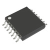 PIC16LF15325T-E/STVAOMicrochip TechnologyIC MCU 8BIT 14KB FLASH 14TSSOP
 PIC16LF15344-I/GZMicrochip TechnologyIC MCU 8BIT 7KB FLASH 20UQFN
 PIC16LF15325-I/PMicrochip TechnologyIC MCU 8BIT 14KB FLASH 14DIP
 PIC16LF15344-I/SOMicrochip TechnologyIC MCU 8BIT 7KB FLASH 20SOIC
 PIC16LF15344T-I/GZMicrochip


