
Manufacturer Part Number
PIC24F16KA101T-I/SS
Manufacturer
microchip-technology
Introduction
The PIC24F16KA101T-I/SS is a high-performance, low-power 16-bit PIC® microcontroller that offers a range of advanced features and capabilities. It is part of the PIC® XLP™ 24F series, designed for applications that require efficient power management and high performance.
Product Features and Performance
32MHz operating speed
Variety of communication interfaces including I2C, IrDA, SPI, and UART/USART
Integrated peripherals such as Brown-out Detect/Reset, POR, PWM, and Watchdog Timer
18 I/O pins
16KB of FLASH program memory
5KB of RAM
512 bytes of EEPROM
9-channel 10-bit ADC
Product Advantages
Optimized for low-power applications with the PIC® XLP™ technology
Wide operating voltage range of 1.8V to 3.6V
Extended temperature range of -40°C to 85°C
Compact 20-SSOP package
Key Reasons to Choose This Product
Excellent performance-to-power ratio for efficient power management
Versatile communication interfaces for seamless integration
Robust set of peripherals for comprehensive system control
Flexible and scalable architecture for a wide range of applications
Quality and Safety Features
Rigorous quality control and testing processes
Compliance with industry standards and regulations
Compatibility
Pin-compatible with other PIC24F microcontrollers in the same series
Supported by Microchip's comprehensive development tools and software ecosystem
Application Areas
Industrial automation and control systems
Home and building automation
Portable and battery-powered devices
Sensor and monitoring applications
Medical and healthcare equipment
Product Lifecycle
The PIC24F16KA101T-I/SS is an active product in Microchip's portfolio. There are several equivalent or alternative models available, including the PIC24F16KA102, PIC24F16KA301, and PIC24F16KA302. For the latest information on product availability and alternative options, please contact our website's sales team.
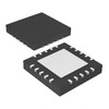 PIC24F16KA101-I/MQMicrochip TechnologyIC MCU 16BIT 16KB FLASH 20VQFN
 PIC24F16KA102-I/MLMicrochip TechnologyIC MCU 16BIT 16KB FLASH 28QFN
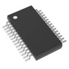 PIC24F16KA102-I/SSMicrochip TechnologyIC MCU 16BIT 16KB FLASH 28SSOP
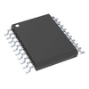 PIC24F16KA101-I/SSMicrochip TechnologyIC MCU 16BIT 16KB FLASH 20SSOP
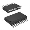 PIC24F16KA101T-I/SOMicrochip TechnologyIC MCU 16BIT 16KB FLASH 20SOIC
 PIC24F16KA101-I/PMicrochip TechnologyIC MCU 16BIT 16KB FLASH 20DIP
 PIC24F16KA102-E/SSMicrochip


