

STM32L063R8T6 (1)
Manufacturer Part Number
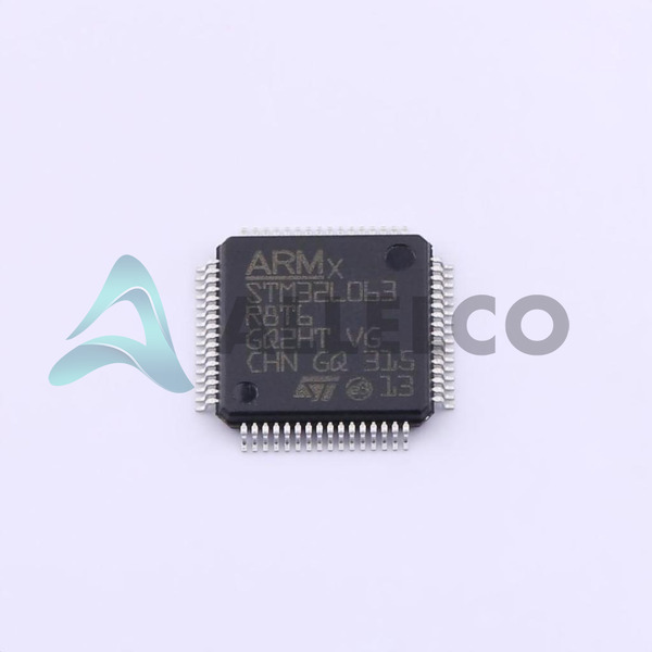
STM32L063R8T6
Manufacturer
STMicroelectronics
Introduction
A 32-bit ARM Cortex-M0+ microcontroller suitable for a wide range of applications, particularly in the low-power and energy-efficient product segment.
Product Features and Performance
ARM Cortex-M0+ core technology
32-bit single-core with a maximum clock speed of 32MHz
Low-power energy-efficient operations
Multi-channel direct memory access (DMA)
Integrated liquid-crystal display (LCD) controller
Pulse-width modulation (PWM) for motor and LED control
Product Advantages
Optimized for low power consumption
High integration with multiple communication interfaces
Robust peripheral set for versatile applications
Enhanced electrostatic discharge (ESD) protection
Wide voltage supply range for flexible power sources
STM32L063R8T6 (2)
Key Technical Parameters
Core Processor: ARM Cortex-M0+
Speed: 32MHz
Number of I/O: 51
Program Memory: 64KB FLASH
EEPROM: 2KB
RAM: 8KB
Data Converters: 16x12-bit A/D, 1x12-bit D/A
Voltage Supply Range: 1.65V to 3.6V
Operating Temperature Range: -40°C to 85°C
Quality and Safety Features
Brown-out detect/reset to prevent improper operation
Programmable watchdog timer (WDT) for system reliability
Protection against unexpected resets (POR)
Compliance with industrial standards for quality and reliability
Compatibility
Full compatibility with the STM32 family
Interfaces include I2C, IrDA, SPI, UART/USART, and USB
Surface mount 64-LQFP package for PCB design flexibility
Internal oscillator to reduce external component count
Application Areas
Consumer electronics
Industrial automation
Battery-operated devices
Internet of Things (IoT) endpoints
Energy management systems
Product Lifecycle
Product status is active
Not near discontinuation
Support and documentation available for long-term projects
Several Key Reasons to Choose This Product
Highly efficient ARM Cortex-M0+ processor enables complex tasks at low energy costs
Flexible peripheral support caters to a diverse set of application needs
Comprehensive support for connectivity options enhances interfacing capabilities
Extended temperature range makes the device suitable for harsh environments
STMicroelectronics' reputation for robustness and quality in microcontroller production


 STM32L062K8U6STMicroelectronicsIC MCU 32BIT 64KB FLASH 32UFQFPN
 STM32L071CBT3TRSTMicroelectronicsIC MCU 32BIT 128KB FLASH 48LQFP
 STM32L053R8T6TRSTMicroelectronicsIC MCU 32BIT 64KB FLASH 64LQFP
 STM32L071CBT6STMicroelectronicsIC MCU 32BIT 128KB FLASH 48LQFP
 STM32L063C8T6STMicroelectronics
 STM32L063C8U6STMicroelectronicsIC MCU 32BIT 64KB FLASH 48UFQFPN
 STM32L071C8T6STMicroelectronicsIC MCU 32BIT 64KB FLASH 48LQFP


