

STM8S207RBT6C (1)
Manufacturer Part Number
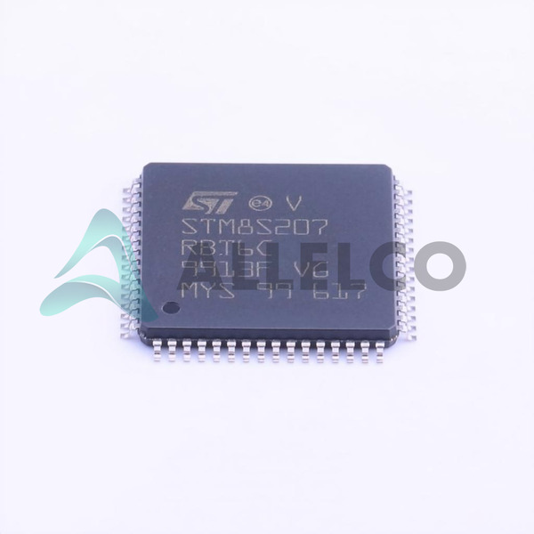
STM8S207RBT6C
Manufacturer
stmicroelectronics
Introduction
The STM8S207RBT6C is a high-performance 8-bit microcontroller from stmicroelectronics, featuring robust connectivity options and extensive memory capacity, suitable for a range of embedded applications.
Product Features and Performance
Core Processor: STM8
Core Size: 8-Bit
Speed: 24MHz
Connectivity: I2C, IrDA, LINbus, SPI, UART/USART
Peripherals include Brown-out Detect/Reset, Power-on Reset, PWM, Watchdog Timer
Number of I/O: 52
Program Memory Size: 128KB
EEPROM Size: 2KB
RAM Size: 6KB
A/D Converters: 16 x 10-bit
Oscillator Type: Internal
Product Advantages
High-speed operation at 24MHz
Extensive data storage capabilities with flash and EEPROM
Integrated safety features like brown-out detect and watchdog timer
Versatile connectivity options for enhanced device interfacing
STM8S207RBT6C (2)
Key Technical Parameters
Voltage Supply: 2.95V to 5.5V
Operating Temperature: -40°C to 85°C
Mounting Type: Surface Mount
Package: 64-LQFP (14x14)
Quality and Safety Features
Brown-out Detect/Reset ensures reliable operation under unstable voltage conditions
Power-on Reset provides a clean start-up sequence
Watchdog Timer helps in system recovery
Compatibility
Compatible with a variety of communication interfaces and protocols
Application Areas
Industrial control systems
Consumer electronics
Automotive products
Telecommunication devices
Product Lifecycle
Current product status: Active
Product is not nearing discontinuation and has available upgrades
Several Key Reasons to Choose This Product
High reliability and robust operational parameters ensure uninterrupted performance
Comprehensive connectivity opens up multiple application design options
Large memory capacity facilitates complex programming and data storage
Wide operating temperature range makes it suitable for harsh environments
Integrative peripherals reduce additional components needed, minimizing design complexity

 STM8S207R8T6STMicroelectronicsIC MCU 8BIT 64KB FLASH 64LQFP
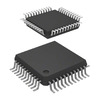 STM8S207S6T6CTRSTMicroelectronicsIC MCU 8BIT 32KB FLASH 44LQFP
 STM8S207S6T6CSTMicroelectronicsIC MCU 8BIT 32KB FLASH 44LQFP
 STM8S207RBT6C,8STMicroelectronics


