
TDA7491MV13TR (1)
Manufacturer Part Number
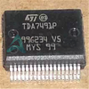
TDA7491MV13TR
Manufacturer
STMicroelectronics
Introduction
The TDA7491MV13TR is a high-performance, single-channel Class D audio power amplifier from STMicroelectronics.
Product Features and Performance
Operates on a supply voltage from 5V to 18V
Delivers up to 25W of output power into a 6Ω load
Features differential inputs, mute function, and protection against short-circuit and thermal overload
Employs advanced Class D amplification technology for high efficiency
Product Advantages
High-power output in a compact package
Robust protection features for reliable operation
Wide operating voltage range for flexibility in system design
Efficient Class D architecture for low power consumption
Key Technical Parameters
Output Power: 25W x 1 @ 6Ω load
Supply Voltage: 5V to 18V
Operating Temperature: -40°C to 85°C
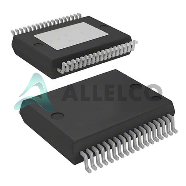
Package: 36-PowerBFSOP (0.295", 7.50mm Width)
Quality and Safety Features
RoHS3 compliant
Short-circuit and thermal protection
Mute function for safe operation
Compatibility
The TDA7491MV13TR is a single-channel Class D audio power amplifier suitable for a wide range of audio applications.
Application Areas
Portable audio devices
Home theater systems
Professional audio equipment
Automotive infotainment systems
Product Lifecycle
The TDA7491MV13TR is an actively supported product from STMicroelectronics. Replacement or upgrade options may be available for future product needs.
Key Reasons to Choose This Product
High-power output in a compact package
Robust protection features for reliable operation
Wide operating voltage range for flexibility in system design
Efficient Class D architecture for low power consumption
RoHS3 compliance for environmental responsibility

 TDA7491PSTMicroelectronicsIC AMP D STEREO 10W POWERSSO36
 TDA7491LPSTMicroelectronicsIC AMP CLSS D STER 5W POWERSSO36
 TDA749213TRSTMicroelectronicsIC AMP D STEREO 50W POWERSSO36
 TDA7490LSTMicroelectronicsIC AMP D MON/STER 40W 25FLEXIWTT
 TDA7492MVSTMicroelectronics


