
TS924AIPT (1)
Manufacturer Part Number
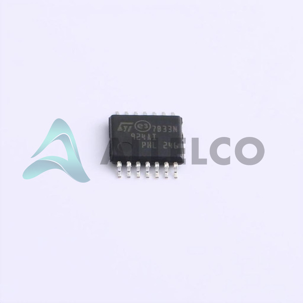
TS924AIPT
Manufacturer
STMicroelectronics
Introduction
Integrated Circuit (IC)
Linear Amplifiers Instrumentation, OP Amps, Buffer Amps
Product Features and Performance
Rail-to-Rail Output
Automotive Grade (AEC-Q100 Qualified)
Quad Operational Amplifier
Gain Bandwidth Product: 4 MHz
Supply Voltage Range: 2.7V to 12V
Supply Current: 1mA
Slew Rate: 1.3V/μs
Input Offset Voltage: 900 μV
Input Bias Current: 15 nA
Output Current per Channel: 80 mA
Wide Operating Temperature Range: -40°C to 125°C
Product Advantages
Automotive-grade performance and reliability
Wide operating voltage and temperature range
Low power consumption
Precise and stable operation
TS924AIPT (2)
Key Technical Parameters
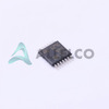
Package: 14-TSSOP
Mounting Type: Surface Mount
RoHS Compliance: RoHS3
Quality and Safety Features
AEC-Q100 Qualified
RoHS3 Compliant
Compatibility
Suitable for various automotive and industrial applications
Application Areas
Automotive electronics
Industrial instrumentation
General-purpose amplifier circuits
Product Lifecycle
Currently in production
Replacement or upgrade options may be available from the manufacturer
Key Reasons to Choose This Product
Automotive-grade performance and reliability
Wide operating voltage and temperature range
Low power consumption
Precise and stable operation
Compact surface-mount package
RoHS3 compliance for environmental friendliness
 TS922IPTSTMicroelectronicsIC OPAMP GP 2 CIRCUIT 8TSSOP
 TS924AINSTMicroelectronicsIC OPAMP GP 4 CIRCUIT 14DIP
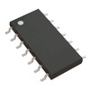
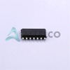 TS924IDTSTMicroelectronicsIC OPAMP GP 4 CIRCUIT 14SO
 TS922IYPTSTMicroelectronicsIC OPAMP GP 2 CIRCUIT 8TSSOP
 TS922IYDTSTMicroelectronicsIC OPAMP GP 2 CIRCUIT 8SOIC
 TS922INSTMicroelectronicsIC OPAMP GP 2 CIRCUIT 8MINI DIP
 TS924IDSTMicroelectronicsIC OPAMP GP 4 CIRCUIT 14SO
 TS924AITPSTMicroelectronics


