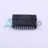
 TDA7266D13TRSTMicroelectronicsIC AMP AB STEREO 5W POWERSO-20
 TDA7269ASTMicroelectronicsIC AMP AB STEREO 14W 11MULTIWATT
 TDA7267STMicroelectronicsIC AMP CLSS AB MONO 2W 8MINI DIP
 TDA7268STMicroelectronicsIC AMP AB STEREO 2W 16POWERDIP
 TDA7266SSTMicroelectronicsIC AMP AB STEREO 5W 15MULTIWATT
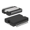 TDA7266DSTMicroelectronicsIC AMP AB STEREO 5W POWERSO-20
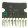 TDA7266SASTMicroelectronicsIC AMP AB STEREO 7W 15CLIPWATT
 TDA7269SASTMicroelectronics
 TDA7265L-J11-A-TUTC
- Nath***rooks
- Jun 11, 2026

Image may be representation.
See specifications for product details.
See specifications for product details.
- EXPRESS OPTION
- Payment method
TDA7266P13TR - STMicroelectronics
- Manufacturer Part Number
- TDA7266P13TR
- Manufacturer
- STMicroelectronics
- Allelco Part Number
- 41D-TDA7266P13TR
- Warranty
- 1 Year Allelco Warranty - Find out more
- Stock Status:
- 16,160 pcs available, New & Original
- Parts Description
- -
- Data sheet
- -
- Category
- Integrated Circuits (ICs) > Specialized ICs
- RoHs Status
- Our certification
- In stock: 16160
- Unit Price: $4.707
- Subtotal: $0.00
Want a better price?
Add to Cart and Submit RFQ now, we'll contact you immediately.
| Quantity | Unit Price | Ext. Price |
|---|---|---|
| 1+ | $4.707 | $4.71 |
| 200+ | $1.879 | $375.80 |
| 500+ | $1.816 | $908.00 |
| 1000+ | $1.784 | $1,784.00 |
The above prices does not include taxes and freight rates, which will be calculated on the order pages.


