4.7 kΩ Resistor Guide: Color Code, Uses, Testing & Value Comparison
A 4.7 kΩ resistor is a common electronic part used to control current and set voltage in circuits. This article explains what the value means, how to read its color bands, and what its main specifications are. It also shows where it is normally used, such as pull-up and pull-down signals, transistor control, and voltage dividers. You will also learn how to check it using a multimeter and how it compares with 10 kΩ and 47 kΩ resistors.Catalog

Figure 1. 4.7 kΩ Axial Resistor
What is a 4.7 kΩ Resistor?
A 4.7 kΩ resistor is a resistor with a resistance value of 4,700 ohms (Ω). The “kΩ” means kilo-ohms, so 4.7 kΩ = 4.7 × 1,000 Ω = 4,700 Ω. In a circuit, this value is commonly used to reduce current to a safer level or to set a voltage level at a node. It helps keep signals stable by controlling how much current can flow through a path. In simple terms, a 4.7 kΩ resistor is a standard value used to control current or shape voltage without letting the circuit draw too much.
Electrical Specifications of a 4.7 kΩ Resistor
A 4.7 kΩ resistor can be made in many types and sizes, so its specifications vary by series and manufacturer. The table below lists common, measurable specs you’ll see on datasheets.
|
Specifications |
Typical Range |
|
Nominal
resistance |
4.7 kΩ (4,700
Ω) |
|
Tolerance |
±0.1%, ±0.5%,
±1%, ±2%, ±5% |
|
Power rating
(axial) |
1/8 W, 1/4 W,
1/2 W, 1 W, 2 W |
|
Power rating
(SMD) |
1/20 W, 1/16
W, 1/10 W, 1/8 W, 1/4 W |
|
Temperature
coefficient (TCR) |
25, 50, 100,
200, 300 ppm/°C |
|
Operating
temperature range |
−55°C to
+155°C (varies by type) |
|
Max working
voltage |
~50 V to 500
V (depends on package/power) |
|
Max overload
voltage |
Higher than
working voltage (series-dependent) |
|
Package size
(SMD) |
0201, 0402,
0603, 0805, 1206, 1210 |
|
Body size
(axial) |
Depends on
wattage (longer body for higher W) |
|
Resistor
technology |
Thick film,
thin film, metal film, wirewound |
|
Long-term
stability |
e.g., ±(0.2%
to 1%) over 1,000 hrs (type-dependent) |
|
Noise
(relative) |
Lower in
metal/thin film, higher in some thick film |
|
Voltage
coefficient |
Typically
low; specified more in precision types |
|
Moisture /
environmental rating |
Varies
(general-purpose to high-reliability series) |
4.7 kΩ Resistor Color Code
Many 4.7 kΩ resistors use color bands so you can identify the value quickly. The band count (4, 5, or 6) mainly changes how many digits are shown and whether extra info like temperature coefficient is included.
4-Band Color Code
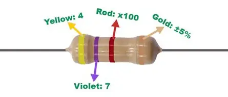
Figure 2. 4-Band 4.7 kΩ Color Code
|
Band
Position |
Color |
Meaning |
Value |
|
1st band |
Yellow |
1st digit |
4 |
|
2nd band |
Violet |
2nd digit |
7 |
|
3rd band |
Red |
Multiplier |
×100 (10²) |
|
4th band |
Gold |
Tolerance |
±5% |
The first two bands give the number 47. The third band (red) means multiply by 100, so 47 × 100 = 4,700 Ω. That is 4.7 kΩ. The gold band shows the resistance can vary by ±5% from the stated value.
5-Band Color Code
A 5-band resistor adds an extra digit, so the value uses three significant digits before the multiplier. This is commonly used for tighter tolerance parts.
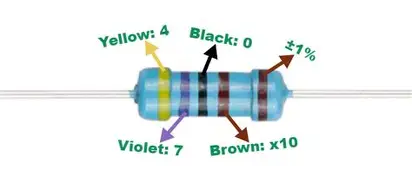
Figure 3. 5-Band 4.7 kΩ Color Code
|
Band
Position |
Color |
Meaning |
Value |
|
1st band |
Yellow |
1st digit |
4 |
|
2nd band |
Violet |
2nd digit |
7 |
|
3rd band |
Black |
3rd digit |
0 |
|
4th band |
Brown |
Multiplier |
×10 (10¹) |
|
5th band |
Brown |
Tolerance |
±1% |
The first three bands form 470. The multiplier band (brown) means ×10, so 470 × 10 = 4,700 Ω. That equals 4.7 kΩ. The last band (brown) indicates ±1% tolerance, which is generally more precise than common 4-band parts.
6-Band Color Code
A 6-band resistor includes a temperature coefficient (tempco) band in addition to tolerance. This is useful when you care about value stability as temperature changes.
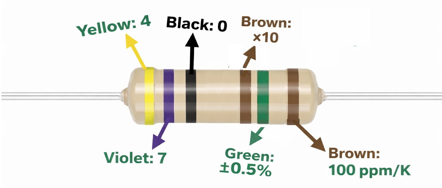
Figure 4. 6-Band 4.7 kΩ Color Code
|
Band
Position |
Color |
Meaning |
Value |
|
1st band |
Yellow |
1st digit |
4 |
|
2nd band |
Violet |
2nd digit |
7 |
|
3rd band |
Black |
3rd digit |
0 |
|
4th band |
Brown |
Multiplier |
×10 (10¹) |
|
5th band |
Green |
Tolerance |
±0.5% |
|
6th band |
Brown |
Tempco |
100 ppm/°C |
The green band means the resistor is allowed to vary by ±0.5% from 4.7 kΩ. The brown tempco band means the resistance changes about 100 ppm/°C, which is 0.01% per °C (because 100 ppm = 100/1,000,000). Lower ppm/°C values usually mean better stability when temperatures rise or fall. This is why 6-band resistors are often used where consistent resistance matters over temperature.
Applications of a 4.7 kΩ Resistor
A 4.7 kΩ resistor is a “middle” value that fits many practical designs, especially around logic signals and small-signal circuits. Below are common ways it is used in circuits.
1. Pull-up resistor for digital inputs
A 4.7 kΩ pull-up helps a digital input read a clean HIGH when the switch or output is open. It gives a strong enough pull-up to fight small noise, but it still keeps current reasonable when the line is pulled LOW. This value is widely seen on microcontroller inputs and open-drain outputs. It is also common on shared signal lines where stability matters.
2. Pull-down resistor for stable LOW state
A 4.7 kΩ pull-down holds a signal at LOW when nothing is driving it. This prevents “floating” inputs that can randomly change state. It is often used with buttons, sensor outputs, and enable pins. The value is strong enough to define a clear level without making the circuit heavy.
3. Transistor biasing in small-signal stages
In BJT or MOSFET driver sections, 4.7 kΩ is often used to set a bias path for a base/gate node. It helps control how strongly a control signal drives the transistor input. Many choose it when they want a firm control path without excessive drive current. It also helps keep the input from staying charged when the driving signal disconnects.
4. Voltage divider for reference or sensing nodes
A 4.7 kΩ resistor is commonly paired with another resistor to form a divider for a predictable node voltage. It is used for input scaling, reference setting, and sensor readout circuits. The value is practical because it does not require very large components and still keeps divider current moderate. It’s also easy to match with many standard resistor values.
5. Signal line damping or mild loading
In some signal paths, 4.7 kΩ is used as a light load to reduce unwanted floating or to shape a node’s behavior. It can help calm small noise pickup on high-impedance lines. This is common around analog inputs and comparator inputs. The goal is a steadier node without turning it into a heavy load.
How to Test a 4.7 kΩ Resistor Using a Multimeter?
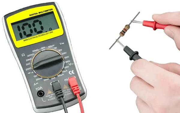
Figure 5. Measuring a Resistor Using a Digital Multimeter
A quick multimeter check confirms whether a resistor is near its expected value. This is helpful when troubleshooting or sorting parts.
Step 1: Set up the multimeter correctly
Turn the multimeter on and set it to the resistance (Ω) mode. If your meter is manual-range, select a range above 4.7 kΩ, such as 20 kΩ. Make sure the probes are plugged into the correct ports (COM and Ω). Touch the probe tips together briefly to see that the meter responds normally.
Step 2: Isolate the resistor before measuring
For the most accurate reading, the resistor should be measured out of circuit. If it is still soldered on a board, other parts can create parallel paths that change the reading. If removal is not possible, lift one leg of the resistor so it is no longer fully connected. This step prevents false readings that look too low.
Step 3: Measure the resistance value
Hold one probe on each lead of the resistor. Keep steady contact so the value does not jump due to poor connection. Read the displayed resistance and note whether it is close to 4.70 kΩ. A small drift is normal depending on the resistor’s tolerance.
Step 4: Judge the result using an expected range
Compare the reading to the resistor’s tolerance if you know it. For a common ±5% part, a normal range is about 4.465 kΩ to 4.935 kΩ. For a ±1% part, a normal range is about 4.653 kΩ to 4.747 kΩ. If the meter shows OL (open line) or a value far outside the expected range, the resistor may be damaged or the measurement setup may be wrong.
Comparing 4.7 kΩ vs 10 kΩ vs 47 kΩ Resistors
These three values are often used for the same “jobs” (like pull-ups, bias paths, and dividers), but they behave differently because resistance changes current and loading. The table below shows practical electrical differences and when each value is usually chosen.
|
Features |
4.7 kΩ |
10 kΩ |
47 kΩ |
|
Current at 5
V (I = V/R) |
1.06 mA |
0.50 mA |
0.106 mA |
|
Current at 12
V |
2.55 mA |
1.20 mA |
0.255 mA |
|
Resistance
ratio to 4.7 kΩ |
1× |
2.13× higher |
10× higher |
|
Voltage drop
across resistor at 1 mA |
4.7 V |
10 V |
47 V |
|
Power dissipation
at 5 V (P = V²/R) |
5.32 mW |
2.50 mW |
0.53 mW |
|
Power
dissipation at 12 V |
30.6 mW |
14.4 mW |
3.06 mW |
|
RC time
constant with 100 nF capacitor |
0.47 ms |
1.00 ms |
4.70 ms |
|
RC cutoff
frequency with 100 nF (fc = 1/2πRC) |
339 Hz |
159 Hz |
33.9 Hz |
|
Current
change per 1 V increase |
0.213 mA/V |
0.100 mA/V |
0.0213 mA/V |
|
Output
impedance contribution in divider |
Low |
Medium |
High |
|
Charging time
to 63% with 100 nF |
0.47 ms |
1.00 ms |
4.70 ms |
|
Charging time
to ~99% (≈5τ) |
2.35 ms |
5.00 ms |
23.5 ms |
|
Typical ADC
source impedance effect |
Minimal error |
Acceptable
error |
Noticeable
error possible |
|
Sensitivity
to leakage current (1 µA leakage error) |
0.47% error |
1.0% error |
4.7% error |
|
Relative
signal settling speed |
Fast |
Moderate |
Slow |
Conclusion
The 4.7 kΩ resistor gives a balanced resistance that works well in many circuits. Its color code shows its value and accuracy, and a multimeter test confirms if it still works properly. It is often used to keep signals stable, control transistor inputs, and create fixed voltage levels. Compared to lower or higher values, it draws a moderate current and stays reliable, which is why it is widely used.
About us
ALLELCO LIMITED
Read more
Quick inquiry
Please send an inquiry, we will respond immediately.
Frequently Asked Questions [FAQ]
1. Which type is better: carbon film or metal film 4.7 kΩ resistor?
Metal film is usually better because it is more stable, less noisy, and more accurate. Carbon film is cheaper and acceptable for simple circuits.
2. Can a 4.7 kΩ resistor be used in Arduino or microcontroller projects?
Yes, it is widely used for I²C pull-ups, button inputs, transistor drivers, and signal conditioning. It provides a good balance between current use and signal reliability.
3. What happens if I use a resistor with too low wattage?
The resistor may overheat, change value, or burn out. This can also damage nearby components or cause unstable circuit operation.
4. Are SMD and axial 4.7 kΩ resistors electrically the same?
Yes, the resistance value is the same. The difference is only size, mounting style, and power rating capability.
5. Can temperature affect the performance of a 4.7 kΩ resistor?
Yes. Heat changes resistance slightly. Precision resistors with low temperature coefficient maintain stable values in warm environments.
XC3042-100PC84C PLCC84 Package, Logic Blocks, and Performance
on February 18th
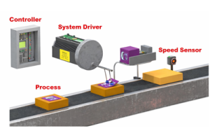
Introduction to Control Systems: Working, Types and Applications
on February 16th
Popular Posts
-

Complex Instruction Set Computers: How They Changed Computing?
on April 17th 147710
-

USB-C Pinout and Features
on April 17th 111651
-

Using Xilinx Unified Simulation Primitives: A Comprehensive Guide to FPGA Design and Simulation
on April 17th 111314
-

Power Supply Voltages in Electronics: Meaning of VCC, VDD, VEE, VSS, and GND
on April 17th 83575
-

RJ45 Connector Guide: Pinout, Wiring, Cable Types, and Uses
on January 1th 79214
-

The Ultimate Guide to Wire Color Codes in Modern Electrical Systems
The way our electrical systems use colors isn’t just for looks. Each wire color now indicates a specific function, making it easier to identify and handle electrical components correctly during ins...on January 1th 66745
-

Quality (Q) Factor: Equations and Applications
The quality factor, or 'Q', is important when checking how well inductors and resonators work in electronic systems that use radio frequencies (RF). 'Q' measures how well a circuit minimizes energy...on January 1th 62923
-

Purge Valve Guide: Function, Symptoms, Testing, and Replacement for Optimal Engine Performance
The purge valve is a key part of a car’s system that helps keep the air clean by managing fuel vapors before they can escape into the atmosphere. This not only helps the environment by reducing pol...on January 1th 62792
-

Achieving Peak Performance with the Maximum Power Transfer Theorem
The Maximum Power Transfer Theorem explains how energy from a source, such as a battery or generator, flows to a connected load. It shows the exact condition where the load receives the most power....on January 1th 54020
-

A23 Battery Specifications and Compatibility
The A23 battery is a small, cylinder-shaped battery with high voltage. Also called 23A, 23AE, or MN21, it runs at 12 volts and much higher than AA or AAA batteries. Its special design make...on January 1th 51934
HOT Part Number
-
MP4423GQ-Z
Monolithic Power Systems Inc.
IC REG BUCK ADJUSTABLE 3A 8QFN
XC6201P452PR-G
Torex Semiconductor Ltd
IC REG LINEAR 4.5V 250MA SOT89
XTR116UA/2K5
Texas Instruments
IC CURRENT TRANSMITTER 8SOIC
TPS2013AD
Texas Instruments
IC PWR SWITCH N-CHAN 1:1 8SOIC
1812AA271KAT1A
KYOCERA AVX
CAP CER 270PF 1KV NP0 1812
1N1196R
Solid State Inc.
DIODE GEN PURP REV 400V 40A DO5
DS1230Y-120+
Analog Devices Inc./Maxim Integrated
IC NVSRAM 256KBIT PAR 28EDIP
CL21C122JBFNNNG
Samsung Electro-Mechanics
CAP CER 1200PF 50V C0G/NP0 0805
2N6798
Microsemi Corporation
MOSFET N-CH 200V 5.5A TO39
MAX6710DUT
Analog Devices Inc./Maxim Integrated
MAX6710 LOW-VOLTAGE, HIGH-ACCURA
SY88703VKC
Microchip Technology
IC LIMIT AMP 10MSOP
IXBH16N170
IXYS
IGBT 1700V 40A 250W TO247AD
MK64FX512VDC12
NXP USA Inc.
IC MCU 32BIT 512KB FLSH 121XFBGA
ISO7731DBQ
Texas Instruments
DGTL ISO 3000VRMS 3CH GP 16SSOP
1S2838-T1B
Renesas Electronics America Inc
HIGH SPEED DOUBLE DIODE
LT1460EIS8-2.5#PBF
Analog Devices Inc.
IC VREF SERIES 0.125% 8SOIC
74ACTQ32SJX
onsemi
IC GATE OR 4CH 2-INP 14SOP
06035C392JAT2A
KYOCERA AVX
CAP CER 3900PF 50V X7R 0603 -
KSZ8441HLI
Microchip Technology
IC ETHERNET CTRLR 10/100 64LQFP
MRF7S19080HR5
NXP USA Inc.
FET RF 65V 1.99GHZ NI-780
APX810-31SRG-7
Diodes Incorporated
IC SUPERVISOR 1 CHANNEL SOT23R
5V41235PGGI8
Renesas Electronics America Inc
IC CLK GEN SPRED SPECTRM 16TSSOP
GRM033R61C183ME84D
Murata Electronics
CAP CER 0.018UF 16V X5R 0201
AP1501A-T5L-U
Diodes Incorporated
IC REG BUCK ADJ 5A TO220-5
AP2820GMMTR-G1
Diodes Incorporated
IC PWR SWITCH N-CHAN 1:1 8MSOP
HMC1031MS8ETR
Analog Devices Inc.
IC CLOCK GEN INT-N PLL 8-MS8E
TPS7B6933QDCYRQ1
Texas Instruments
IC REG LIN 3.3V 150MA SOT223-4
MAX1793EUE25+T
Analog Devices Inc./Maxim Integrated
IC REG LIN POS ADJ 1A 16TSSOP
LCMXO1200C-5TN100C
Lattice Semiconductor Corporation
IC FPGA 73 I/O 100TQFP
TSV6192AID
STMicroelectronics
IC CMOS 2 CIRCUIT 8SOIC
AT89C5115-TISUM
Microchip Technology
IC MCU 8BIT 16KB FLASH 28SOIC
NE5517D
onsemi
IC OPAMP TRANSCOND 2 CIRC 16SOIC
170M1418
Eaton - Bussmann Electrical Division
FUSE SQUARE 125A 700VAC RECT
STW45NM60
STMicroelectronics
MOSFET N-CH 650V 45A TO247-3
TMS320VC5509AZHH
Texas Instruments
IC FIXED POINT DSP 179-BGA
MAX352CPE
Analog Devices Inc./Maxim Integrated
IC SWITCH SPST-NOX4 35OHM 16DIP -

LAN91C110-PU
Microchip Technology
IC ETHERNET CTLR MAC PHY 144TQFP
OPB706B
onsemi
SWITCH IR SLOTTED TRANS PC MNT
2SK3820-DL-1E
onsemi
MOSFET N-CH 100V 26A TO263-2
1812AA221KATBE
KYOCERA AVX
CAP CER 220PF 1KV C0G/NP0 1812
FDS6064N7
Fairchild Semiconductor
MOSFET N-CH 20V 23A 8SO
FCP150N65F
onsemi
MOSFET N-CH 650V 24A TO220-3
AFE8405IZDQ
Texas Instruments
RF RCVR 14BIT ADC 484BGA
ISL83082EIBZ-T
Intersil
IC TRANSCEIVER HALF 1/1 8SOIC
HM2R70PA5108N9LF
Amphenol ICC (FCI)
CONN RECEPT 132POS 2MM PRESS-FIT
SM6T68CA
STMicroelectronics
TVS DIODE 58.1VWM 121VC SMB
DS92LV16TVHG
Texas Instruments
IC SERDES LVDS 16BIT BUS 80-LQFP
1704671038
Molex
IMPACT 3X8 UNGUIDED 100OHM DC .3
EL7583IREZ-T13
Renesas Electronics America Inc
IC REG CONV LCD 2OUT 20HTSSOP
ERJ-8ENF3011V
Panasonic Electronic Components
RES SMD 3.01K OHM 1% 1/4W 1206
FQB11P06TM
onsemi
MOSFET P-CH 60V 11.4A D2PAK
SMBJ16AHE3/5B
Electro-Films (EFI) / Vishay
TVS DIODE 16V 26V DO214AA
PGA-105+
Mini-Circuits
IC AMP CATV 40MHZ-2.6GHZ SOT89
ADP2302ARDZ
Analog Devices Inc.
IC REG BUCK ADJUSTABLE 2A 8SOIC