
A Practical Guide to Varistors
Voltage spikes can quietly damage electronic circuits, even when everything seems to be working fine. That’s where varistors come in. They sit in a circuit and stay out of the way until voltage rises beyond what’s expected. When that happens, they react fast and help limit the stress seen by other parts. In this guide, you’ll learn what a varistor is, how it behaves when voltage changes, the different types you might come across, and where it’s commonly used. By the end, you’ll have a clear picture of how varistors fit into real electronic designs.Catalog
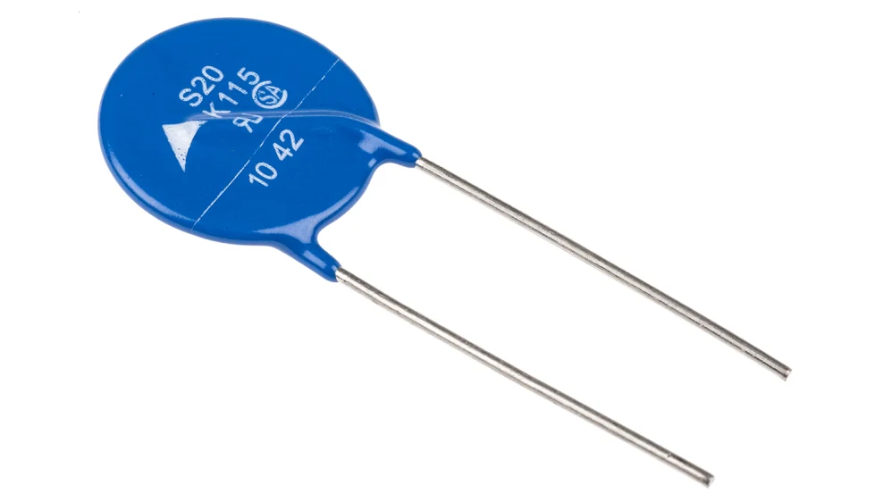
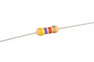
Figure 1. Disc-Type Varistor Component
What Is a Varistor?
A varistor is an electronic component whose resistance changes according to the voltage applied across it. The term comes from variable resistor, reflecting its voltage-dependent nature. Unlike fixed resistors, a varistor does not maintain a constant resistance during operation.
At normal voltage levels, a varistor exhibits very high resistance and allows only minimal current to pass. When the applied voltage exceeds a defined threshold, the resistance decreases rapidly. This response occurs inherently within the material and does not rely on external control, adjustment, or switching.
This voltage-sensitive behavior defines the fundamental identity of a varistor. Its electrical characteristics are nonlinear, meaning the relationship between voltage and resistance is not proportional. The device remains largely inactive during standard operation and changes state only when voltage rises beyond its intended range.
How a Varistor Works
A varistor changes its resistance based on the applied voltage. Under normal conditions, it remains at high resistance and does not affect circuit operation.
Voltage-Dependent Resistance Behavior
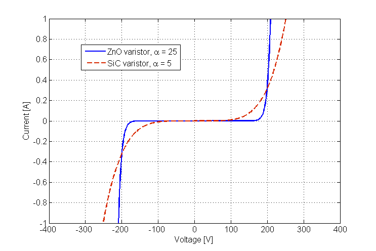
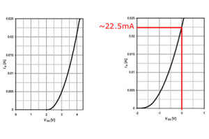
Figure 2. Varistor Current–Voltage Characteristics
A varistor operates based on a nonlinear relationship between voltage and current. At low and normal voltage levels, the device maintains very high resistance, which allows only a minimal amount of current to pass. In this region, changes in voltage produce little change in current, so the varistor remains largely inactive within the circuit.
As the applied voltage increases and approaches a defined threshold voltage, the electrical behavior begins to shift. Once this threshold is exceeded, the resistance of the varistor decreases sharply, and the current rises rapidly. This change does not occur gradually. Instead, it happens within a narrow voltage range, which is a defining characteristic of voltage-dependent resistors.
The sharpness of this transition reflects the degree of nonlinearity of the material used. Some varistors show a steeper rise in current for a small increase in voltage, while others respond in a more moderate way. This behavior is commonly expressed using a general current–voltage relationship written as I = k · Vα, where the exponent indicates how strongly the current responds to voltage changes. A higher value corresponds to a more abrupt transition.
This nonlinear resistance behavior allows the varistor to remain electrically unobtrusive during normal operation, while responding decisively when voltage rises beyond its intended range.
Response During a Voltage Surge

Figure 3. Varistor Operation During a Voltage Surge
When a sudden voltage spike occurs, the varistor responds automatically as the applied voltage exceeds its defined threshold. At this point, the device transitions from a high-resistance state to a low-resistance conductive state, allowing excess current to flow through it rather than continuing along the normal circuit path.
As current is redirected, the voltage across the connected circuit is limited to a lower level. This limiting action reduces the peak voltage experienced during the surge. The change in conduction occurs rapidly and lasts only for the duration of the voltage spike.
During this brief interval, part of the surge energy is absorbed by the varistor material and dissipated internally. Once the voltage returns to its normal range, the varistor exits the conductive state and returns to high resistance, effectively restoring its original electrical condition.
Types of Varistors
Metal Oxide Varistors (MOVs)
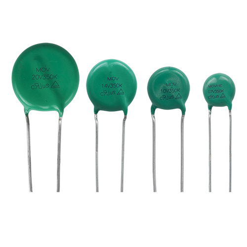
Figure 4. Metal Oxide Varistor (MOV) Types
Metal oxide varistors are the most widely used type in modern electronic systems. They are constructed from a ceramic material composed primarily of zinc oxide grains, which form a network of junctions within the device. This structure gives MOVs their strong nonlinear resistance behavior.
MOVs respond quickly when voltage exceeds a defined level and are capable of absorbing large amounts of surge energy. Because of this combination of fast response and high energy handling, they are commonly used for general-purpose surge protection. Typical applications include power lines, power supplies, household electronics, and commercial electrical equipment.
Silicon Carbide Varistors (SiC Varistors)
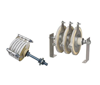
Figure 5. Silicon Carbide Varistors for High Power
Silicon carbide varistors are designed for high-voltage and high-power environments. They can tolerate strong electrical stress and are suitable for circuits exposed to large voltage variations. However, under normal operating voltage, these devices exhibit higher leakage current compared to other varistor types.
Due to this characteristic, silicon carbide varistors are less suitable for low-voltage or precision electronic circuits. They are more commonly found in industrial systems where higher standby current is acceptable and robust voltage handling is required.
Multilayer Varistors (MLVs)
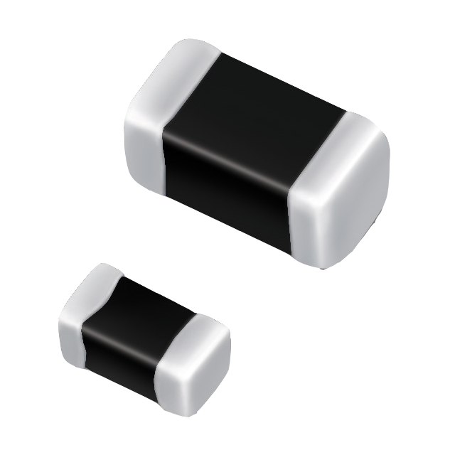
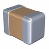
Figure 6. Multilayer Varistor Surface-Mount Packages
Multilayer varistors are compact devices designed primarily for surface-mount applications. They use multiple thin ceramic layers stacked together to achieve voltage-dependent resistance in a much smaller physical size than traditional disk-type varistors.
MLVs are best suited for low-energy transient protection. They are widely used in portable electronics, communication equipment, and densely populated circuit boards where space is limited. Their small size makes them practical for modern electronic designs that require localized protection.
Low-Capacitance Varistors
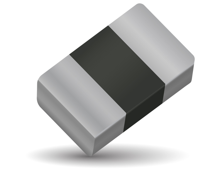
Figure 7. Low-Capacitance Varistor for Signal Lines
Low-capacitance varistors are optimized for use in signal and communication lines. These devices are designed to minimize capacitance so they do not interfere with signal quality. Low capacitance is important in circuits where high-speed signals, audio data, or digital communication must remain undistorted.
Because standard varistors can affect signal integrity, low-capacitance versions are commonly used in data interfaces, audio connections, and communication ports where maintaining signal clarity is critical.
High-Energy Varistors for Industrial Use

Figure 8. High-Energy Varistor for Industrial Protection
High-energy varistors are built to handle large surge currents and high pulse energy. These devices are physically larger and designed for demanding electrical environments. Their construction allows them to absorb strong transient events without immediate failure.
Such varistors are typically used in industrial power systems, heavy machinery, and AC mains protection. Their role is to provide robust protection in applications where electrical surges are frequent or particularly severe.
How to Choose the Right Varistor
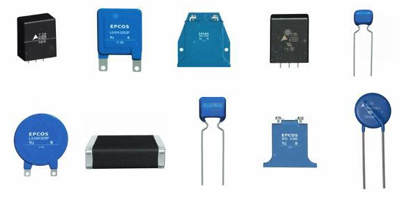
Figure 9. Common Varistor Package Variations
Selecting the right varistor is important because it directly affects how well a circuit is protected and how safely it operates. A poorly chosen varistor may fail to limit voltage properly or may degrade quickly under stress, reducing its protective value.
The selection process begins with understanding the normal operating voltage of the circuit. The varistor must be rated above this level so it remains inactive during normal operation. At the same time, its response level must be low enough to react when abnormal voltage conditions occur.
Another key factor is the expected surge conditions. Different circuits are exposed to different surge strengths, durations, and frequencies. Choosing a varistor with suitable energy and current handling capability ensures it can withstand these events without damage.
Physical and application constraints also matter. Space limitations, connection type, and whether the varistor is used on a power line or signal line all influence the choice. Careful selection helps balance effective protection, long-term reliability, and overall circuit safety.
Advantages and Limitations of Varistors
| Advantages | Limitations |
| Fast response to voltage transients | Degrades with repeated surge exposure |
| Simple and passive device operation | Limited lifespan under frequent surges |
| High surge current handling capability | Not suitable for long-duration overvoltage |
| Effective voltage clamping for short transients | Clamping voltage shifts downward over time |
| Wide range of voltage and energy ratings | Can fail in short-circuit mode |
| Easy to integrate into circuits | Requires proper coordination with fuses |
| Low cost compared to other protection devices | Generates heat during surge events |
| Available in many package sizes | Performance affected by temperature extremes |
| Suitable for AC and DC applications | Leakage current increases as device ages |
| High energy absorption in compact form | Not ideal for precision signal protection |
Common Applications of Varistors
Figure 10. Varistors Used in Power and Control Circuits
Varistors are widely used in electronic systems where protection against unexpected voltage spikes is required. One of the most common applications is in power supplies, where they help limit sudden voltage increases that could damage internal components. They are also a key element in surge protectors and power strips, providing protection for connected devices during transient events on the mains supply.
In consumer electronics, varistors are used to protect circuits in devices such as televisions, computers, chargers, and home appliances. These products are often connected directly to power lines, making them vulnerable to voltage disturbances that varistors are designed to handle.
Varistors are also found in industrial equipment, where electrical systems are exposed to higher power levels and more frequent switching events. In these environments, they help protect control circuits, motor drives, and power distribution systems from voltage stress.
In automotive systems, varistors are used to manage voltage spikes caused by inductive loads, such as motors and solenoids, and by fluctuations in the vehicle’s electrical system. Their ability to respond quickly makes them suitable for protecting sensitive electronic modules in modern vehicles.
Varistor Symbols and Circuit Placement
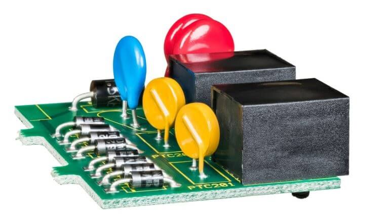
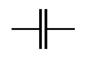
Figure 11. Varistor Circuit Symbol
In circuit diagrams, a varistor is shown using a resistor-based symbol that indicates its voltage-dependent resistance. This symbol distinguishes it from a fixed resistor and signals that the component responds to changes in voltage rather than current alone.
Varistors are commonly placed directly across the lines that require protection. In power circuits, this usually means a connection between supply lines or between a supply line and ground. In signal circuits, the device is typically connected between the signal line and ground.
Correct placement ensures that the varistor can respond promptly to excessive voltage at the point where it appears. Locating the component close to the protected line helps limit the voltage seen by the circuit during transient events.
Conclusion
Varistors play a quiet but important role in protecting electronic circuits from sudden voltage changes. You’ve seen how their resistance changes with voltage and why that behavior makes them useful for handling spikes. Different varistor types exist to match different voltage levels, energy demands, and circuit constraints. Choosing the right one helps improve reliability and reduce the risk of damage. When placed correctly, a varistor can absorb stress that would otherwise reach sensitive parts. Understanding how they work makes it easier for you to use them confidently in everyday electronics.
About us
ALLELCO LIMITED
Read more
Quick inquiry
Please send an inquiry, we will respond immediately.
Frequently Asked Questions [FAQ]
1. What does a varistor do in a circuit?
A varistor helps limit excessive voltage by changing its resistance when voltage rises beyond a set level.
2. Is a varistor active during normal operation?
No, it remains at high resistance and has little effect on the circuit under normal voltage conditions.
3. Are varistors used in both AC and DC circuits?
Yes, varistors can be used in both AC and DC applications when properly rated.
4. Do varistors wear out over time?
Yes, repeated exposure to voltage surges can gradually reduce their performance.
5. Where should a varistor be placed in a circuit?
It is usually placed across the line or between a line and ground where voltage spikes are expected.
4k7 Resistor Explained: Value, Color Code, Types, and Applications
on January 26th
Depletion-Mode MOSFET: Types, Characteristics, Biasing, and Applications
on January 26th
Popular Posts
-

Complex Instruction Set Computers: How They Changed Computing?
on June 11th 148369
-

USB-C Pinout and Features
on June 11th 131089
-

Using Xilinx Unified Simulation Primitives: A Comprehensive Guide to FPGA Design and Simulation
on June 11th 111849
-

Power Supply Voltages in Electronics: Meaning of VCC, VDD, VEE, VSS, and GND
on June 11th 94098
-

RJ45 Connector Guide: Pinout, Wiring, Cable Types, and Uses
on January 1th 93471
-

The Ultimate Guide to Wire Color Codes in Modern Electrical Systems
The way our electrical systems use colors isn’t just for looks. Each wire color now indicates a specific function, making it easier to identify and handle electrical components correctly during ins...on January 1th 76626
-

Quality (Q) Factor: Equations and Applications
The quality factor, or 'Q', is important when checking how well inductors and resonators work in electronic systems that use radio frequencies (RF). 'Q' measures how well a circuit minimizes energy...on January 1th 74625
-

Purge Valve Guide: Function, Symptoms, Testing, and Replacement for Optimal Engine Performance
The purge valve is a key part of a car’s system that helps keep the air clean by managing fuel vapors before they can escape into the atmosphere. This not only helps the environment by reducing pol...on January 1th 68562
-
Understanding Capacitors and Their Symbols in Circuit Diagrams
Capacitors are small parts used in almost all electronic devices. They store and release electrical energy and are found in things like power supplies, radios, and circuits that help reduce noise. ...on June 11th 58352
-

A23 Battery Specifications and Compatibility
The A23 battery is a small, cylinder-shaped battery with high voltage. Also called 23A, 23AE, or MN21, it runs at 12 volts and much higher than AA or AAA batteries. Its special design make...on January 1th 57907
HOT Part Number
-
C2012X5R2E472M085AA
TDK Corporation
CAP CER 4700PF 250V X5R 0805
DS1708ESA/T&R
Analog Devices Inc./Maxim Integrated
IC SUPERVISOR 1 CHANNEL 8SOIC
LM79L12ACZ
Texas Instruments
IC REG LINEAR FIXED NEG STND
BCM56842A1KFTBLG
Broadcom Limited
MULTI LAYER SWITCH
QRF1220T30
Powerex Inc.
DIODE MODULE 1.2KV 99A
LD39100PU12RY
STMicroelectronics
IC REG LINEAR 1.2V 1A 6DFN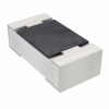
RT0402BRD072K4L
Yageo
RES SMD 2.4K OHM 0.1% 1/16W 0402
ZUS1R52412
Cosel USA, Inc.
DC DC CONVERTER 12V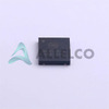
NCV51411MNR2G
onsemi
IC REG BUCK ADJ 1.5A 18DFN
PN5179
onsemi
RF TRANS NPN 12V 2GHZ TO92-3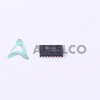
FXLA108BQX
onsemi
IC TRANSLTR BIDIRECTIONAL 20DQFN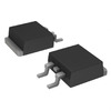
VS-20ETS08STRLPBF
Vishay General Semiconductor - Diodes Division
DIODE GEN PURP 800V 20A TO263AB
2SJ645-E
onsemi
P-CHANNEL SMALL SIGNAL MOSFET
C5750X5R2E684M230KA
TDK Corporation
CAP CER 0.68UF 250V X5R 2220
NJM2240M
Nisshinbo Micro Devices Inc.
IC VIDEO SGNL QUAD 8DMP
BV1HJ045EFJ-CE2
Rohm Semiconductor
BUILT-IN OUTPUT DIAGNOSIS 1CH HI
BRT21H
Infineon Technologies
TRIAC OUTPUT OPTOCOUPLER WITH ZE
SMS7630-079LF
Skyworks Solutions Inc.
RF DIODE SCHOTTKY 1V 75MW SC79 -
MAX9374AEKA+T
Analog Devices Inc./Maxim Integrated
IC TRANSLATOR UNIDIR SOT23-8
GRM1555C2A3R8CA01D
Murata Electronics
CAP CER 3.8PF 100V C0G/NP0 0402
1N5355B
NTE Electronics, Inc
DIODE ZENER 18V 5W AXIAL
SWPA6045S100MT
Shenzhen Sunlord Electronics Co., Ltd.
FIXED IND 10UH 2.45A 62MOHM SMD
MBRT30020
GeneSiC Semiconductor
DIODE MODULE 20V 150A 3TOWER
IP4058CX8/LF,135
NXP USA Inc.
FILTER RC(PI) ESD SMD
MCR8DCNT4G
onsemi
SILICON CONTROLLED RECTIFIER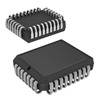
CY7C419-15JXC
Infineon Technologies
IC ASYNC FIFO MEM 256X9 32-PLCC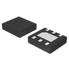
NCP692MN18T2G
onsemi
IC REG LINEAR 1.8V 1A 6DFN
UPA2211T1M-T1-AT
Renesas Electronics America Inc
MOSFET P-CH 12V 7.5A 8VSOF
0603YC392JAT2A
KYOCERA AVX
CAP CER 3900PF 16V X7R 0603
AT45DB041B-TI
Microchip Technology
IC FLASH 4MBIT SPI 20MHZ 28TSOP
RT1206DRE0790KL
YAGEO
RES SMD 90K OHM 0.5% 1/4W 1206
GRM0335C2A8R9CA01D
Murata Electronics
CAP CER 8.9PF 100V C0G/NP0 0201
06035A3R3C4T2A
KYOCERA AVX
CAP CER 3.3PF 50V NP0 0603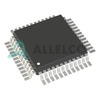
L99PD08
STMicroelectronics
IC PWR DRIVER N-CHAN 1:8 32LQFP
AD9748ACPZRL7
Analog Devices Inc.
IC DAC 8BIT A-OUT 32LFCSP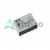
OZ-SS-124L1
TE Connectivity Potter & Brumfield Relays
RELAY GEN PURPOSE SPDT 16A 24V -

CL21A106KAYNNNE
Samsung Electro-Mechanics
CAP CER 10UF 25V X5R 0805
FWP-50A14FA
Eaton - Bussmann Electrical Division
FUSE CARTRIDGE 50A 700VAC/800VDC
MCP6561RT-E/OT
Microchip Technology
IC COMPARATOR 1 GEN PUR SOT23-5
MC13203FC
NXP USA Inc.
IC RF TXRX 802.15.4 32VFQFN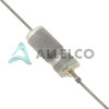
135D685X9125C6
Vishay Sprague
CAP TANT 6.8UF 10% 125V AXIAL
08052U430KAT2A
KYOCERA AVX
CAP CER 43PF 200V NP0 0805
CDBU0230
Comchip Technology
DIODE SCHOTTKY 30V 200MA 0603C
NCP603SNADJT1G
onsemi
IC REG LIN POS ADJ 300MA 5TSOP
MIC5219-3.3BMM
Microchip Technology
IC REG LINEAR 3.3V 500MA 8MSOP
SI501-PROG-CAX
Silicon Labs
MEMS OSC PROG BLANK 32KHZ-100MHZ
MAX232ESE
Analog Devices Inc./Maxim Integrated
RS-232 DRIVER/RECEIVER
SN74LV10ADR
Texas Instruments
IC GATE NAND 3CH 3-INP 14SOIC
AP7365-30WG-7
Diodes Incorporated
IC REG LINEAR 3V 600MA SOT25
M2S060TS-FGG484I
Microchip Technology
IC SOC CORTEX-M3 166MHZ 484FBGA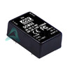
DCW03A-12
MEAN WELL USA Inc.
DC DC CONVERTER +/-12V 3W
C4532JB1E106M250KA
TDK Corporation
CAP CER 10UF 25V JB 1812
S9S12VR64AF0MLF
NXP USA Inc.
IC MCU 16BIT 64KB FLASH 48LQFP
ISL6561IRZ
Renesas Electronics America Inc
IC REG CTRLR INTEL 4OUT 40QFN