FPGA vs Microcontroller: Key Differences You Should Know
When working with PCB design, you will often choose between an FPGA and a microcontroller based on your system needs. This article explains what each one is, how they work, and the key components inside them. You will also see how their system structures and programming approaches differ. By understanding these basics, you can decide which one fits your project better.Catalog
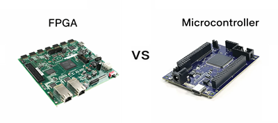
Figure 1. FPGA vs Microcontroller Overview
What is an FPGA and a Microcontroller?
An FPGA (Field-Programmable Gate Array) is a type of integrated circuit that allows you to configure digital logic after manufacturing. It is widely used in PCB design when custom hardware behavior is needed, such as creating parallel signal processing paths or specialized control logic. Instead of running software instructions, an FPGA builds hardware circuits based on your design. This makes it suitable for tasks that require precise timing and flexibility at the hardware level. In a PCB system, it acts as a programmable logic core that connects to memory, sensors, and communication interfaces. Use FPGA devices to directly implement custom digital systems on the board.
A microcontroller is a compact integrated circuit designed to execute programmed instructions to control electronic systems. It typically includes a processor, memory, and input/output interfaces in a single chip, making it ideal for embedded PCB applications. Microcontrollers are commonly used to read inputs, process data, and control outputs such as LEDs, motors, or sensors. They operate sequentially, following a set of instructions written in software. In PCB design, they serve as the main control unit for many devices, from simple gadgets to complex systems. Their simplicity and integration make them a popular choice for control-oriented tasks.
Components of FPGA and Microcontroller
FPGA Components
• Logic Blocks (Configurable Logic Blocks - CLBs)
These are the core building units of an FPGA that perform digital operations. Each logic block contains lookup tables (LUTs), flip-flops, and multiplexers. LUTs are used to implement combinational logic functions by storing truth tables. Flip-flops provide storage for sequential logic and timing control. Together, these elements allow the FPGA to form custom digital circuits.
• Programmable Interconnects
Interconnects are routing paths that connect different logic blocks within the FPGA. They allow signals to travel between logic elements based on the configured design. These connections are flexible and can be reprogrammed to match different circuit layouts. The routing network ensures that signals reach the correct destinations efficiently. This structure enables complex circuit creation without fixed wiring.
• Input/Output (I/O) Blocks
I/O blocks connect the FPGA to external components on the PCB. They handle communication with devices such as sensors, memory, and processors. These blocks support different voltage levels and signaling standards. They can be configured as input, output, or bidirectional ports. This flexibility allows seamless integration with various external systems.
• Clock Management Units
Clock management units control timing and synchronization inside the FPGA. They generate and distribute clock signals to different parts of the chip. These units may include phase-locked loops (PLLs) or delay-locked loops (DLLs). They help maintain stable timing for reliable operation. Proper clock control ensures accurate data processing across the design.
• Embedded Memory Blocks (BRAM)
These are built-in memory units used for temporary data storage. They allow fast access to frequently used data within the FPGA. Block RAM can be configured in different sizes and modes. It supports buffering, caching, and data handling tasks. This reduces the need for external memory in some designs.
Microcontroller Components
• Central Processing Unit (CPU)
The CPU is the main processing unit that executes instructions. It performs arithmetic, logic, and control operations. The CPU reads instructions from memory and processes them step by step. It manages the flow of data within the system. This makes it the core controller of the microcontroller.
• Memory (Flash, RAM, EEPROM)
Microcontrollers include different types of memory for storing code and data. Flash memory stores the program permanently. RAM is used for temporary data during execution. EEPROM is used for storing small amounts of non-volatile data. Each type plays a specific role in system operation. Together, they support reliable data handling.
• Timers and Counters
Timers and counters are used for time-based operations. They help generate delays, measure time intervals, and control periodic tasks. These components are important for functions like PWM signal generation. They also support event counting and scheduling. This makes them useful in control and automation systems.
• Input/Output Ports (GPIO)
GPIO pins allow the microcontroller to interact with external devices. They can be configured as input or output depending on the application. These ports read signals from sensors or send signals to actuators. They support digital communication with other components. GPIOs are good for system connectivity.
• Communication Interfaces
Microcontrollers include built-in communication modules such as UART, SPI, and I2C. These interfaces allow data exchange with other devices. They support serial communication protocols commonly used in embedded systems. This enables connection to sensors, displays, and other controllers. These interfaces simplify system integration.
Block Diagrams of FPGA and Microcontroller Systems
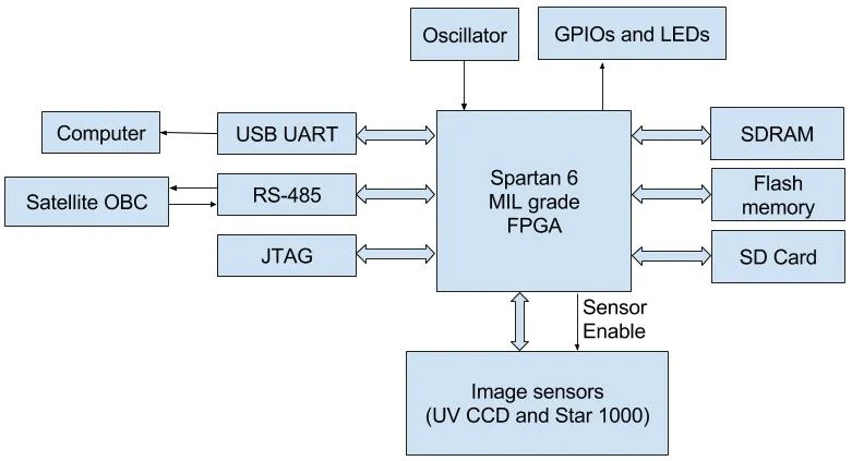
Figure 2. FPGA Block Diagram
The FPGA block diagram shows a central programmable device connected to multiple external components through flexible interfaces. It typically links to memory modules such as SDRAM and flash storage for data handling. Communication interfaces like UART, RS-485, and JTAG allow interaction with external systems and debugging tools. The diagram also includes input/output connections for sensors and control signals. A clock source provides timing signals to ensure synchronized operation. The structure highlights how the FPGA acts as a central logic hub in the system. It manages data flow between peripherals without fixed internal architecture.
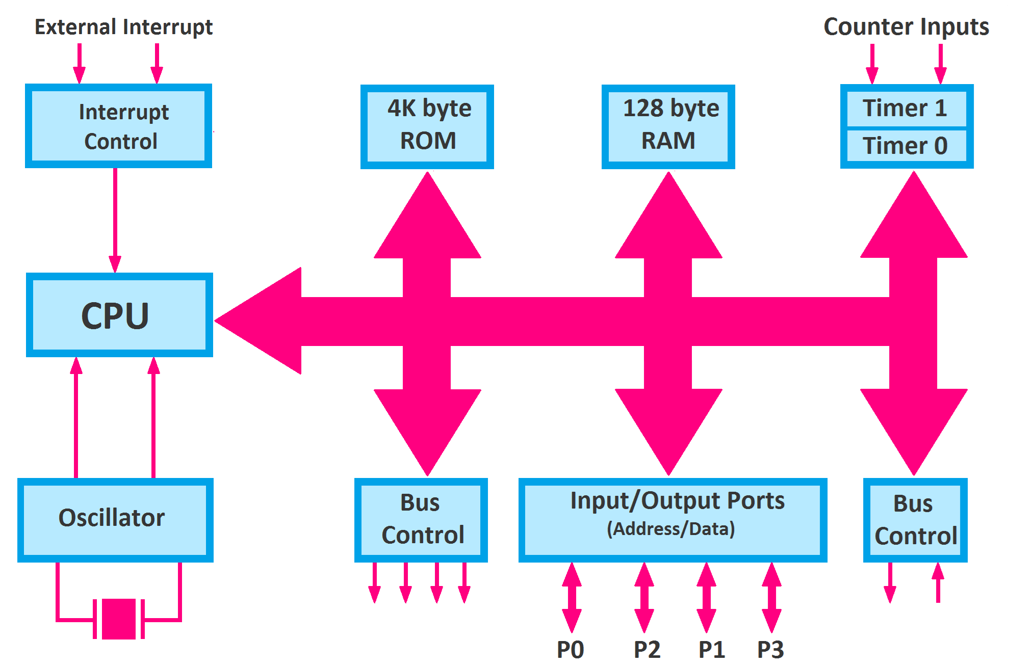
Figure 3. Microcontroller Block Diagram
The microcontroller block diagram shows a centralized processing unit connected to internal memory and peripherals through a bus system. The CPU communicates with ROM and RAM to execute and store instructions. Input/output ports allow interaction with external devices such as sensors and displays. Timers and counters handle timing-related operations within the system. An oscillator provides the clock signal that drives the entire operation. Interrupt control manages external and internal event handling. This structure shows a compact and integrated system designed for control tasks.
Advantages and Disadvantages of FPGA
|
Advantages |
Disadvantages |
|
Highly flexible
hardware configuration allows custom digital circuit design. |
Complex design
process requiring hardware description languages. |
|
Supports true
parallel processing for high-speed operations. |
Higher cost
compared to simpler embedded solutions. |
|
Reprogrammable
multiple times for different applications. |
Longer
development time due to design and testing. |
|
Can handle
complex signal processing and data tasks. |
Requires
specialized tools and expertise. |
|
Scalable
architecture suitable for advanced systems. |
Higher power
consumption in some designs. |
Advantages and Disadvantages of Microcontrollers
|
Advantages |
Disadvantages |
|
Low cost and
widely available for many applications. |
Limited
processing power for complex tasks. |
|
Easy to program
using common languages like C/C++. |
Sequential
execution limits parallel processing. |
|
Integrated
components reduce external hardware needs. |
Limited memory
compared to larger systems. |
|
Low power
consumption suitable for portable devices. |
Less flexible
hardware configuration. |
|
Fast development
cycle for embedded systems. |
Performance
depends on fixed architecture. |
Code Comparison: FPGA vs Microcontroller Programming
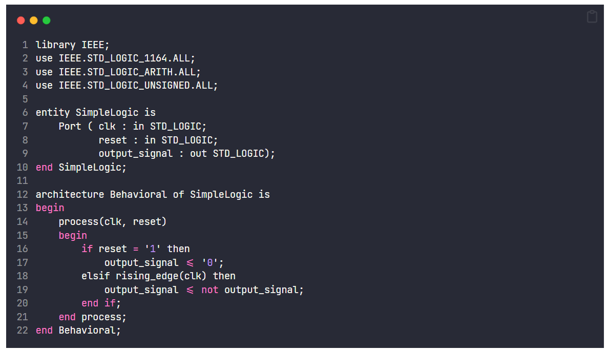
The FPGA code example uses a hardware description language such as VHDL to define circuit behavior. Instead of writing instructions, the code describes how signals change and interact. It defines inputs, outputs, and how the system responds to clock signals. The structure includes entities and architectures to organize the design. A process block controls how signals update based on events like clock edges. This approach models hardware behavior directly rather than executing sequential commands. It allows the creation of custom digital logic inside the FPGA.
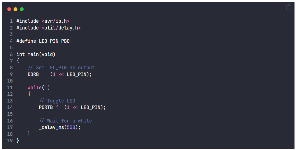
The microcontroller code example uses a programming language such as C to execute instructions step by step. It begins by setting up hardware registers and defining pin configurations. The main function runs continuously, performing tasks in a loop. Instructions control outputs like turning an LED on and off. Delay functions are used to create timing effects. This approach follows a sequential execution model. It is simple and widely used for embedded system programming.
Applications of FPGA and Microcontrollers
1. Industrial Automation Systems
FPGAs are used for control and signal processing in industrial machines. They handle high-speed data and precise timing requirements. Microcontrollers manage sensors, motors, and control logic in automation systems. Together, they enable reliable and efficient operations. This combination improves system performance and control.
2. Consumer Electronics
Microcontrollers are widely used in devices like washing machines, TVs, and remote controls. They manage user inputs and system functions efficiently. FPGAs are used in advanced devices requiring fast data handling, such as video processing units. These applications benefit from compact and efficient designs. Both technologies support modern electronic products.
3. Communication Systems
FPGAs are used in networking equipment for data routing and signal processing. They support high-speed communication protocols. Microcontrollers handle control and monitoring functions in communication devices. These roles ensure stable and efficient data transmission. This is important in modern communication infrastructure.
4. Medical Devices
Microcontrollers control functions in devices like heart monitors and infusion pumps. They ensure reliable and low-power operation. FPGAs are used in imaging systems for fast data processing. These applications require accuracy and reliability. Both technologies support healthcare systems.
5. Automotive Systems
Microcontrollers manage engine control units, sensors, and safety systems. They ensure efficient vehicle operation. FPGAs are used in advanced driver assistance systems for data processing. These systems improve safety and performance. Automotive electronics rely heavily on both technologies.
6. Aerospace and Defense
FPGAs are used for high-speed data processing and secure communication systems. They support complex signal analysis and control tasks. Microcontrollers handle monitoring and control functions in embedded systems. These applications require high reliability and precision. Both technologies play key roles in mission-critical systems.
FPGA vs Microcontroller vs CPLD
|
Features |
FPGA |
Microcontroller |
CPLD |
|
Logic Resources |
~10K to >10M
logic gates (or LUTs) |
Not applicable
(CPU-based) |
~1K to ~100K
gates |
|
Clock Speed |
~50 MHz to 500+
MHz (design-dependent) |
~1 MHz to 600
MHz (typical MCUs) |
~50 MHz to 200
MHz |
|
Processing Style |
True parallel
hardware execution |
Sequential
instruction execution |
Limited parallel
logic |
|
Configuration
Method |
SRAM/Flash-based
bitstream loaded at startup |
Firmware stored
in Flash memory |
Non-volatile
configuration (EEPROM/Flash) |
|
Programming
Language |
VHDL, Verilog
(HDL) |
C, C++, Assembly |
VHDL, Verilog |
|
Internal Memory |
Block RAM: ~10
KB to several MB |
Flash: ~8 KB–2
MB, RAM: ~2 KB–512 KB |
Very limited
(few KB equivalent) |
|
I/O Pins |
~50 to 1000+
configurable I/Os |
~6 to 200 GPIO
pins |
~30 to 500 I/Os |
|
Power
Consumption |
~1 W to 10+ W
(depends on size/design) |
~1 mW to 500 mW |
~10 mW to 1 W |
|
Boot Time |
ms to seconds
(needs configuration load) |
µs to ms
(instant from Flash) |
Instant
(non-volatile) |
|
Design Entry |
Hardware circuit
definition |
Software program
development |
Logic design
(simpler than FPGA) |
|
External
Components |
Often requires
external memory (DDR, Flash) |
Minimal (usually
standalone) |
Minimal external
components |
|
Reconfiguration |
Fully
reprogrammable, unlimited cycles |
Reprogrammable
firmware |
Reprogrammable
but limited size |
|
Typical Use
Scale |
High-complexity
digital systems |
Small to medium
embedded systems |
Small control
and interface logic |
|
Development
Cycle |
Weeks to months |
Days to weeks |
Days to weeks |
Conclusion
FPGAs and microcontrollers differ mainly in how they process data, with FPGAs offering parallel hardware-based execution and microcontrollers relying on sequential software control. Their internal components, system structures, and programming methods reflect these differences, making each suitable for specific applications. FPGAs excel in high-speed, customizable logic tasks, while microcontrollers are ideal for control-oriented and cost-efficient designs. Together, they play important roles across industries such as automation, communication, automotive, and healthcare systems.
About us
ALLELCO LIMITED
Read more
Quick inquiry
Please send an inquiry, we will respond immediately.
Frequently Asked Questions [FAQ]
1. Can an FPGA replace a microcontroller in a PCB design?
Yes, but it depends on the application. An FPGA can replicate control functions, but it is often more complex and costly compared to a microcontroller for simple tasks.
2. Why are microcontrollers more power-efficient than FPGAs?
Microcontrollers are optimized for low-power operation with integrated components and sleep modes. FPGAs consume more power due to configurable logic and parallel processing.
3. Do FPGAs require an operating system like microcontrollers?
No, FPGAs do not require an operating system because they implement hardware logic directly. Microcontrollers can run without an OS but may use one for complex applications.
4. Can you use both FPGA and microcontroller in one system?
Yes, many systems combine both. The FPGA handles high-speed processing, while the microcontroller manages control and communication tasks.
5. What programming languages are used for FPGA and microcontroller development?
FPGAs use hardware description languages like VHDL or Verilog, while microcontrollers are typically programmed using C or C++.
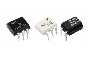
Complete Guide to Optocouplers for Beginners
on March 30th
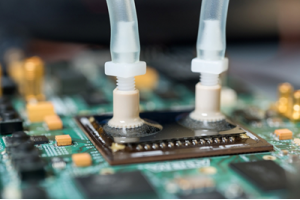
Heat Sink Attachment Methods for PCBs and Selection Guide
on March 27th
Popular Posts
-

Complex Instruction Set Computers: How They Changed Computing?
on April 17th 147712
-

USB-C Pinout and Features
on April 17th 111678
-

Using Xilinx Unified Simulation Primitives: A Comprehensive Guide to FPGA Design and Simulation
on April 17th 111315
-

Power Supply Voltages in Electronics: Meaning of VCC, VDD, VEE, VSS, and GND
on April 17th 83582
-

RJ45 Connector Guide: Pinout, Wiring, Cable Types, and Uses
on January 1th 79229
-

The Ultimate Guide to Wire Color Codes in Modern Electrical Systems
The way our electrical systems use colors isn’t just for looks. Each wire color now indicates a specific function, making it easier to identify and handle electrical components correctly during ins...on January 1th 66753
-

Quality (Q) Factor: Equations and Applications
The quality factor, or 'Q', is important when checking how well inductors and resonators work in electronic systems that use radio frequencies (RF). 'Q' measures how well a circuit minimizes energy...on January 1th 62927
-

Purge Valve Guide: Function, Symptoms, Testing, and Replacement for Optimal Engine Performance
The purge valve is a key part of a car’s system that helps keep the air clean by managing fuel vapors before they can escape into the atmosphere. This not only helps the environment by reducing pol...on January 1th 62801
-

Achieving Peak Performance with the Maximum Power Transfer Theorem
The Maximum Power Transfer Theorem explains how energy from a source, such as a battery or generator, flows to a connected load. It shows the exact condition where the load receives the most power....on January 1th 54022
-

A23 Battery Specifications and Compatibility
The A23 battery is a small, cylinder-shaped battery with high voltage. Also called 23A, 23AE, or MN21, it runs at 12 volts and much higher than AA or AAA batteries. Its special design make...on January 1th 51950
HOT Part Number
-

SBR3045CTFP
Diodes Incorporated
DIODE ARRAY SBR 45V 15A ITO220AB
SN75ALS180D
Texas Instruments
IC TRANSCEIVER FULL 1/1 14SOIC
IXTQ62N15P
IXYS
MOSFET N-CH 150V 62A TO3P
S-1155B18-U5T1G
ABLIC Inc.
IC REG LINEAR 1.8V 500MA SOT89-5
THS6012IDWP
Texas Instruments
IC DRIVER 2/0 20SOPWRPAD
LTC1442IS8#PBF
Analog Devices Inc.
IC COMPARATOR 2 W/VOLT REF 8SO
HCPL-0531#500
Broadcom Limited
OPTOISO 3.75KV 2CH TRANS 8SOIC
LM2576HVSX-15
Texas Instruments
IC REG BUCK 15V 3A TO263-5
P6KE11A
Littelfuse Inc.
TVS DIODE 9.4VWM 15.6VC DO204AC
CM453232-R22ML
Bourns Inc.
FIXED IND 220NH 665MA 250MOHM SM
FQPF6N60
onsemi
MOSFET N-CH 600V 3.6A TO220F
LDK120C33R
STMicroelectronics
IC REG LIN 3.3V 200MA SOT323-5
MGA-30989-BLKG
Broadcom Limited
IC RF AMP GPS 2GHZ-6GHZ SOT89-3
IPP80R900P7
Infineon Technologies
IPP80R900 - 800V COOLMOS N-CHANN
ADM232LJN
Analog Devices Inc.
IC TRANSCEIVER FULL 2/2 16DIP
ADUC7021BCPZ32-RL7
Analog Devices Inc.
IC MCU 16/32B 32KB FLASH 40LFCSP
GCM3195C1H432JA16D
Murata Electronics
CAP CER 4300PF 50V C0G/NP0 1206
VSSR2001103JUF
Vishay Dale Thin Film
RES ARRAY 19 RES 10K OHM 20SSOP -

ADS7841ESQDBQRQ1
Texas Instruments
IC ADC 12BIT SAR 16SSOP
1.5KE36A
Diotec Semiconductor
TVS D5.4X7.5 30.8V 1500W UNI
MB95F272HPF-G-SNE2
Infineon Technologies
IC ANALOG
R5S72623P144FP#UZ
Renesas Electronics America Inc
IC MCU 32BIT
GBJ801-F
Diodes Incorporated
BRIDGE RECT 1PHASE 100V 8A GBJ
MAX1005EEE+T
Analog Devices Inc./Maxim Integrated
IC UNDERSAMPLER IF 16-QSOP
IRFB52N15DPBF
Infineon Technologies
MOSFET N-CH 150V 51A TO220AB
170M7651
Eaton - Bussmann Electrical Division
FUSE 5000A 1000V 24SBKS/90 WAR
ADUM140E1WBRWZ
Analog Devices Inc.
DGTL ISO 3750VRMS 4CH GP 16SOIC
MC912D60ACFU8
NXP USA Inc.
IC MCU 16BIT 60KB FLASH 80QFP
C1005JB1A154M050BC
TDK Corporation
CAP CER 0.15UF 10V JB 0402
ISL32175EIBZ
Renesas Electronics America Inc
IC RECEIVER 0/4 16SOIC
AD571JD
Analog Devices Inc.
IC ADC 10BIT SAR 18CDIP
MC100EL04D
onsemi
IC GATE AND/NAND ECL 2INP 8SOIC
SQ2361ES-T1_GE3
Vishay Siliconix
MOSFET P-CH 60V 2.8A SSOT23
MB354W
Micro Commercial Co
BRIDGE RECT 1P 400V 35A MB-35W
TLV320AIC23IPW
Texas Instruments
IC AUDIO CODEC 32BIT SER 28TSSOP
VE-J43-CZ
Vicor Corporation
DC DC CONVERTER 24V 25W -

LNK414EG
Power Integrations
IC LED DRV OFFL PWM ESIP-7C
DS90C383AMTDX
Texas Instruments
IC TRANSCEIVER 1/1 56TSSOP
NCP585DSN12T1G
onsemi
IC REG LINEAR 1.2V 300MA SOT23-5
BZT52C36LP-7
Diodes Incorporated
DIODE ZENER 36V 250MW 2DFN
FDB120N10
onsemi
MOSFET N-CH 100V 74A D2PAK
SIP4610ADT-T1-E3
Vishay Siliconix
IC PWR SWTCH P-CHAN 1:1 TSOT23-5
MKL02Z16VFG4
NXP USA Inc.
IC MCU 32BIT 16KB FLASH 16QFN
12107C183MAT2A
KYOCERA AVX
CAP CER 0.018UF 500V X7R 1210
PS9121-F3-A
CEL
OPTOISO 3.75KV OPN COLLECTOR 5SO
ATTINY2313V-10SI
Microchip Technology
IC MCU 8BIT 2KB FLASH 20SOIC
BAS70-05,215
NXP USA Inc.
NOW NEXPERIA BAS70-05 - RECTIFIE
MPC8548ECVJAUJD
NXP USA Inc.
IC MPU MPC85XX 1.333GHZ 783BGA
TPS62173DSGR
Texas Instruments
IC REG BUCK 5V 500MA 8WSON
RT0805DRD07360KL
YAGEO
RES SMD 360K OHM 0.5% 1/8W 0805
9ZXL1231AKILFT
Renesas Electronics America Inc
VFQFPN 9.00X9.00X0.90 MM, 0.50MM
DDTB122TC-7-F
Diodes Incorporated
TRANS PREBIAS PNP 200MW SOT23-3
SMAJ51
Littelfuse Inc.
TVS DIODE 51VWM 86.52VC DO214AC
ICM7242IBAZ-T
Renesas Electronics America Inc
IC OSC BINARY CTC PROG 8-SOIC