Complete Guide to Optocouplers for Beginners
When working with electronic circuits, you often need to transfer signals while keeping parts safely isolated. This article explains what an optocoupler is, how it works using light, and what components are inside it. You will also learn about its symbol, pin configuration, different types, and key specifications. In addition, it covers its advantages, limitations, common uses, and how it compares with relays and transformers.Catalog

Figure 1. Optocoupler
What is an Optocoupler?
An optocoupler, also called an opto-isolator, is an electronic component used to transfer signals between two circuits while keeping them electrically isolated. It uses light to pass information, which prevents direct electrical connection between the input and output sides. This isolation helps protect sensitive components from voltage spikes, noise, and ground loops. Optocouplers are widely used in power electronics, control systems, and communication interfaces.
The main purpose of an optocoupler is to ensure safety and signal integrity in electronic designs. By separating high-voltage and low-voltage circuits, it reduces the risk of damage and interference. It also improves system reliability by preventing unwanted current flow between circuits. In modern PCB design, optocouplers are great for achieving safe and stable signal transmission.
Structure of an Optocoupler
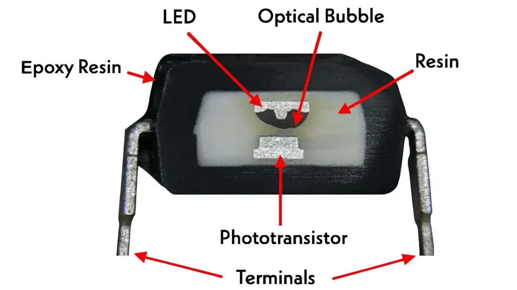
Figure 2. Internal Structure of an Optocoupler
• LED (Light Emitting Diode)
The LED is the input-side component that produces light when current flows through it. It is usually made from infrared-emitting semiconductor material for efficient signal transfer. The LED is positioned to directly face the photodetector inside the package. Its main role is to convert electrical input signals into light energy.
• Phototransistor (Photodetector)
The phototransistor is placed on the output side and detects the light emitted by the LED. It converts the received light into an electrical signal. This component is sensitive to light intensity, which controls its output behavior. It is commonly used due to its good balance of sensitivity and simplicity.
• Optical Bubble / Light Path
The optical space between the LED and photodetector allows light to travel without electrical contact. This region ensures complete electrical isolation between the two sides. It is carefully designed to maximize light transmission efficiency. The clear path helps maintain stable and accurate signal transfer.
• Epoxy Resin (Encapsulation)
The internal components are enclosed in epoxy resin to protect them from moisture, dust, and mechanical damage. This material also helps maintain optical clarity for efficient light transmission. It provides structural stability to the device. The resin ensures long-term reliability in different environments.
• Terminals (Pins)
The terminals provide external electrical connections to the input and output sides. Each pin is assigned for either LED input or photodetector output. They are arranged to maintain isolation spacing. These pins allow easy integration into PCB circuits.
How an Optocoupler Works?
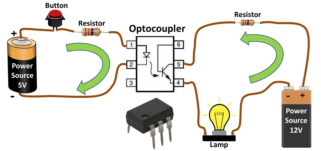
Figure 3. Optocoupler Working Principle
An optocoupler works by converting an electrical signal into light and then back into an electrical signal. When a voltage is applied to the input side, current flows through the LED, causing it to emit light. This light travels across the internal gap without any direct electrical connection. The amount of light produced depends on the input signal strength. This process ensures safe signal transfer between isolated circuits.
On the output side, the photodetector senses the incoming light and responds by generating a corresponding electrical signal. This output signal can then control another circuit, such as switching a load or sending logic data. Because the connection is optical rather than electrical, noise and high voltage cannot pass through. This makes the optocoupler ideal for protection and signal isolation. The overall operation is simple, reliable, and widely used in electronic systems.
Optocoupler Symbol and Pin Configuration

Figure 4. Optocoupler Symbol and Pin Configuration
|
Pin No. |
Pin Name |
Function |
|
1 |
Anode (A) |
Receives
positive input voltage for the LED |
|
2 |
Cathode (K) |
Completes the
LED input circuit |
|
3 |
NC (No
Connection) |
Not internally
connected, reserved or unused |
|
4 |
Emitter (E) |
Output terminal
of phototransistor |
|
5 |
Collector (C) |
Main output
control terminal |
|
6 |
Base (B) |
Optional control
of phototransistor gain |
Types of Optocouplers
Optocouplers are classified based on the type of output device used for signal detection.
Phototransistor Optocoupler
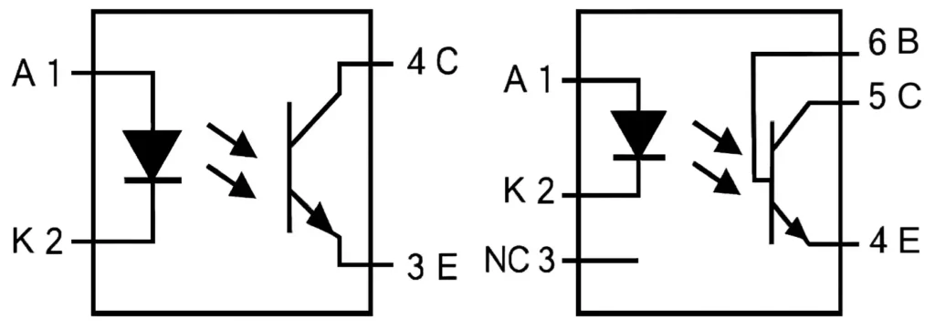
Figure 5. Phototransistor Optocoupler
A phototransistor optocoupler is a type of optocoupler that uses a phototransistor as its output device. It converts light from the internal LED into a controlled electrical output signal. The phototransistor acts like a switch that turns on when it receives light. This type is widely used because it provides good sensitivity and simple circuit design. It is suitable for general-purpose signal isolation and switching tasks. The structure typically shows the LED aligned with a transistor inside the package. Due to its balance of speed and gain, it is commonly used in microcontroller interfacing and low-power control circuits.
Photodiode Optocoupler
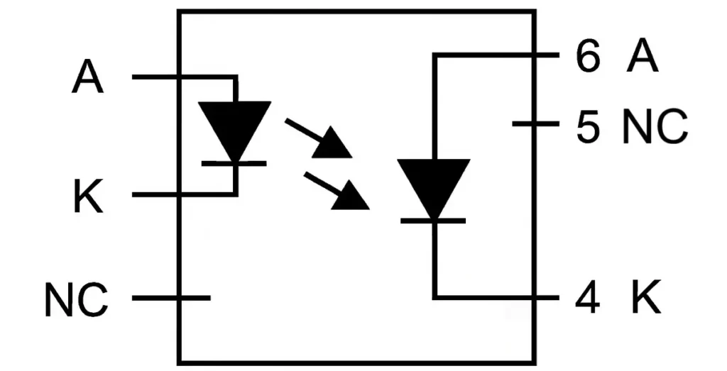
Figure 6. Photodiode Optocoupler
A photodiode optocoupler uses a photodiode as the output sensing element. It converts incoming light into a current with very fast response time. This type is designed for high-speed signal transmission and precise timing applications. The photodiode reacts quickly to light changes, making it ideal for digital communication signals. It usually requires additional amplification for stronger output signals. The internal layout shows a diode aligned with the light source. Its main advantage is speed rather than high output gain.
Photo-Triac Optocoupler
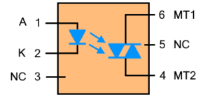
Figure 7. Photo-Triac Optocoupler
A photo-triac optocoupler is an optocoupler that uses a triac as its output device for AC control. It converts light signals into switching action for alternating current loads. When the internal LED is activated, the triac is triggered to conduct current. This allows it to control devices such as lamps, motors, and heaters. The structure typically shows a light source driving a triac output stage. It is widely used in AC switching and dimming applications. This type is important for isolating low-voltage control circuits from high-voltage AC systems.
Photodarlington Optocoupler
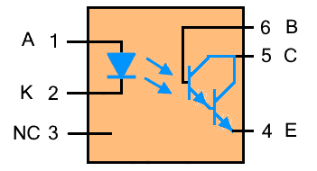
Figure 8. Photodarlington Optocoupler
A photodarlington optocoupler uses a Darlington transistor pair as its output device. It provides higher current gain compared to a standard phototransistor. This allows it to amplify weak light signals into stronger electrical outputs. The internal configuration typically shows two transistors connected to increase sensitivity. It is useful in applications where higher output current is required. However, it operates slower than basic phototransistor types. This design is commonly used in signal amplification and control circuits.
Photo-SCR Optocoupler
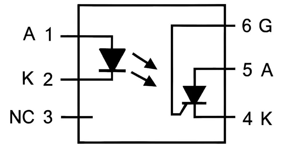
Figure 9. Photo-SCR Optocoupler
A photo-SCR optocoupler uses a silicon-controlled rectifier (SCR) as its output device. It converts light into a latching electrical switching action. Once triggered by light, the SCR remains on until the current drops below a certain level. This makes it suitable for controlled rectification and power control circuits. The internal structure shows a light-driven SCR element. It is commonly used in triggering and protection circuits. This type is ideal for applications that require stable and sustained switching behavior.
Specifications of Optocoupler
|
Parameter |
Typical Range /
Value |
|
Current Transfer
Ratio (CTR) |
50% to 600% (at
IF = 5 mA) |
|
Isolation
Voltage |
2.5 kV to 5 kV
RMS |
|
Forward Voltage
(LED) |
1.1 V to 1.4 V |
|
Forward Current
(IF) |
5 mA to 20 mA
(max up to 50 mA) |
|
Output Current |
1 mA to 50 mA |
|
Switching Speed |
3 µs to 20 µs |
|
Rise Time |
2 µs to 10 µs |
|
Fall Time |
2 µs to 15 µs |
|
Propagation
Delay |
2 µs to 15 µs |
|
Power
Dissipation |
70 mW to 200 mW |
|
Operating Temperature |
-40°C to +85°C |
|
Storage
Temperature |
-55°C to +125°C |
|
Input
Capacitance |
30 pF to 100 pF |
|
Output
Capacitance |
5 pF to 15 pF |
|
Isolation
Resistance |
≥ 10⁹ Ω
(typically 10¹¹ Ω) |
Advantages and Disadvantages of Optocouplers
Advantages of Optocouplers
• Provides strong electrical isolation
• Protects circuits from high voltage spikes
• Reduces electrical noise and interference
• Compact and easy to integrate
• No mechanical wear or moving parts
• Improves system safety and reliability
Limitations of Optocouplers
• Limited current handling capability
• Slower than direct electrical connections
• CTR varies with temperature and aging
• Requires proper input current control
• Not suitable for very high power loads
• Output signal may need amplification
Common Applications of Optocouplers
Optocouplers are widely used in electronic systems where isolation and signal control are required.
1. Power Supply Isolation
Optocouplers are used in switching power supplies to separate high-voltage and low-voltage sections. They help regulate output voltage while maintaining safety. This prevents damage to control circuits. It also ensures stable operation in power conversion systems.
2. Microcontroller Interfacing
They allow microcontrollers to safely interact with high-voltage devices. This protects sensitive logic circuits from electrical stress. It also ensures reliable signal communication. Optocouplers are commonly used in embedded systems.
3. AC Load Switching
Optocouplers control AC devices such as lamps and motors. They provide safe isolation between control signals and power circuits. This improves system safety and durability. They are often used in home automation and industrial control.
4. Signal Isolation in Communication
They isolate communication lines to prevent noise interference. This improves signal clarity and data accuracy. It is useful in industrial communication systems. Isolation helps maintain stable data transmission.
5. Motor Control Circuits
Optocouplers are used in motor drivers to isolate control and power sections. This protects control electronics from voltage spikes. It also improves system reliability. They are widely used in automation systems.
6. Medical Equipment Safety
They ensure patient safety by isolating sensitive circuits. This prevents electrical leakage and hazards. Optocouplers are useful in medical-grade devices. They help meet strict safety standards.
Optocoupler vs Relay vs Transformer
|
Features |
Optocoupler |
Relay |
Transformer |
|
Isolation
Voltage |
2.5–5 kV RMS |
1–10 kV (contact
gap) |
2–15 kV RMS |
|
Switching Method |
LED +
photodetector |
Electromagnetic
contacts |
Magnetic
induction |
|
Switching Speed |
1–20 µs |
5–15 ms |
No switching
(continuous) |
|
Physical Size |
~4–10 mm
(DIP/SMD) |
~10–40 mm |
~20–100 mm |
|
Operating Noise |
0 dB (silent) |
40–60 dB (click
sound) |
0 dB (silent) |
|
Lifespan |
>100,000
hours |
10⁵–10⁷ cycles |
>100,000
hours |
|
Load Capacity |
10–50 mA typical |
1–30 A |
0.1–1000+ VA |
|
Input
Requirement |
5–20 mA (LED
drive) |
5–24 V coil,
10–100 mA |
AC voltage input |
|
Output
Capability |
Low-power signal |
High-power
switching |
AC voltage
transfer |
|
Maintenance |
None |
Contact wear
replacement |
None |
|
Efficiency |
70–90% |
80–90% |
90–98% |
|
EMI Immunity |
>10 kV/µs
CMTI |
Moderate |
High (depends on
design) |
|
Switching
Frequency |
Up to 100 kHz |
<100 Hz |
50–60 Hz typical |
|
Typical Use Case |
Signal
isolation, logic interface |
Power control,
switching loads |
Voltage
conversion, isolation |
Conclusion
Optocouplers play an important role in electronic design by providing electrical isolation, reducing noise, and protecting sensitive circuits from high voltage. Their operation depends on an internal LED and light-sensitive output device, with different types available for switching, signal isolation, amplification, and AC control. Key performance factors, benefits, and limitations must be considered when selecting the right optocoupler for a circuit. Because of their safety, compact size, and reliability, they are widely used in power supplies, control systems, communication interfaces, motor drivers, and medical equipment.
About us
ALLELCO LIMITED
Read more
Quick inquiry
Please send an inquiry, we will respond immediately.
Frequently Asked Questions [FAQ]
1. How do you choose the right optocoupler for a circuit?
You choose based on voltage rating, current transfer ratio (CTR), switching speed, and output type. Match these parameters to your application, such as high-speed communication or power control.
2. What is CTR in an optocoupler and why is it important?
CTR (Current Transfer Ratio) shows how efficiently input current is converted to output current. A higher CTR means stronger output signal, which affects reliability and performance.
3. Can an optocoupler work with both AC and DC signals?
Yes, but it depends on the type. Standard optocouplers handle DC signals, while photo-triac or specialized types are designed for AC applications.
4. How do you test an optocoupler using a multimeter?
You can test the LED side like a diode and check output response by applying input current. A working device should show a change in output when activated.
5. Do optocouplers require external components to work properly?
Yes, they often need resistors to limit input current and sometimes additional components for output amplification or filtering.

Infrared Heaters Explained: Types, Working Principle and Applications
on March 30th
FPGA vs Microcontroller: Key Differences You Should Know
on March 28th
Popular Posts
-

Complex Instruction Set Computers: How They Changed Computing?
on April 17th 147713
-

USB-C Pinout and Features
on April 17th 111758
-

Using Xilinx Unified Simulation Primitives: A Comprehensive Guide to FPGA Design and Simulation
on April 17th 111324
-

Power Supply Voltages in Electronics: Meaning of VCC, VDD, VEE, VSS, and GND
on April 17th 83639
-

RJ45 Connector Guide: Pinout, Wiring, Cable Types, and Uses
on January 1th 79300
-

The Ultimate Guide to Wire Color Codes in Modern Electrical Systems
The way our electrical systems use colors isn’t just for looks. Each wire color now indicates a specific function, making it easier to identify and handle electrical components correctly during ins...on January 1th 66793
-

Quality (Q) Factor: Equations and Applications
The quality factor, or 'Q', is important when checking how well inductors and resonators work in electronic systems that use radio frequencies (RF). 'Q' measures how well a circuit minimizes energy...on January 1th 62957
-

Purge Valve Guide: Function, Symptoms, Testing, and Replacement for Optimal Engine Performance
The purge valve is a key part of a car’s system that helps keep the air clean by managing fuel vapors before they can escape into the atmosphere. This not only helps the environment by reducing pol...on January 1th 62844
-

Achieving Peak Performance with the Maximum Power Transfer Theorem
The Maximum Power Transfer Theorem explains how energy from a source, such as a battery or generator, flows to a connected load. It shows the exact condition where the load receives the most power....on January 1th 54038
-

A23 Battery Specifications and Compatibility
The A23 battery is a small, cylinder-shaped battery with high voltage. Also called 23A, 23AE, or MN21, it runs at 12 volts and much higher than AA or AAA batteries. Its special design make...on January 1th 52019
HOT Part Number
-
MX34016UF1
JAE Electronics
CONN HEADER VERT 16POS 2.2MM
UCLAMP0541Z.TFT
Semtech Corporation
TVS DIODE 5VWM 15VC SLP0603P2X3
AMC1305M25QDWRQ1
Texas Instruments
IC ISOLATED MOD 16BIT 78K 16SOIC
MAX16131WTNN16+T
Analog Devices Inc./Maxim Integrated
IC SUPERVISOR PB DUAL WLP
ATPH33MAHA
Panasonic Electronic Components
CAP TANT POLY 33UF 10V 1206
LT1131ACSW#PBF
Analog Devices Inc.
IC TRANSCEIVER FULL 5/4 28SOIC
AEP18012
Panasonic Electric Works
RELAY SPST 80A 12V
ADS8638SRGET
Texas Instruments
IC ADC 12BIT SAR 24VQFN
AD9632AN
Analog Devices Inc.
IC OPAMP VF ULDIST 70MA 8DIP
CD54HC161F
Harris Corporation
IC BINARY COUNTER 4-BIT 16CDIP
PS32K144UAT0VLLA
NXP USA Inc.
IC MCU 32BIT 512KB FLASH 100LQFP
MAX5151AEEE
Analog Devices Inc./Maxim Integrated
IC DAC 13BIT V-OUT 16QSOP
AOWF4S60
Alpha & Omega Semiconductor Inc.
MOSFET N-CH 600V 4A TO262F
5CSXFC5D6F31C8N
Intel
IC SOC CORTEX-A9 600MHZ 896FBGA
VLCF4018T-100MR74-2
TDK Corporation
FIXED IND 10UH 740MA 188MOHM SMD
LM4130BIM5X-2.0
Texas Instruments
IC VREF SERIES 0.2% SOT23-5
DS31400GN+
Microsemi
IC TIMING DUAL DPLL 256-CSBGA
NLU1G32CMUTCG
onsemi
IC GATE OR 1CH 2-INP 6UDFN -
BD4853G-TR
Rohm Semiconductor
IC SUPERVISOR 1 CHANNEL 5SSOP
TPA2028D1YZFT
Texas Instruments
IC AMP CLASS D MONO 3W 9DSBGA
06031C181JAT2A
KYOCERA AVX
CAP CER 180PF 100V X7R 0603
BAW101S-7
Diodes Incorporated
DIODE ARRAY GP 300V 250MA SOT363
V24A5T400BN
Vicor Corporation
DC DC CONVERTER 5V 400W
MAX7320ATE+
Analog Devices Inc./Maxim Integrated
IC XPNDR 400KHZ I2C 16TQFN
LMR23630ADDAR
Texas Instruments
IC REG BUCK ADJUSTABLE 3A 8SOPWR
LA 130-P
LEM USA Inc.
SENSOR CURRENT HALL 130A AC/DC
LTC2871CUHF#PBF
Analog Devices Inc.
IC TRANSCEIVER FULL 3/3 38QFN
DS4520E+TRL
Analog Devices Inc./Maxim Integrated
IC XPNDR 400KHZ I2C 16TSSOP
744025330
Würth Elektronik
FIXED IND 33UH 400MA 960MOHM SMD
RT1206DRD07240RL
YAGEO
RES SMD 240 OHM 0.5% 1/4W 1206
VE-J03-IX
Vicor Corporation
DC DC CONVERTER 24V 75W
MT42L64M32D1KL-3 IT:A
Micron Technology Inc.
IC DRAM 2GBIT PARALLEL 168FBGA
CM75RL-24NF
Powerex Inc.
IGBT MOD 1200V 75A 520W
MBR10100-BP
Micro Commercial Co
Interface
SRP4020FA-R47M
Bourns Inc.
FIXED IND 470NH 13.2A 6.8MOHM SM
EP2SGX130GF1508I4N
Intel
IC FPGA 734 I/O 1508FBGA -

EMK042CG390JC-FW
Taiyo Yuden
CAP CER 39PF 16V C0G/NP0 01005
MT53E128M32D2DS-046 AAT:A
Micron Technology Inc.
IC DRAM 4GBIT 2.133GHZ 200WFBGA
AD5732AREZ
Analog Devices Inc.
IC DAC 14BIT V-OUT 24TSSOP
SFH620A-1
Vishay Semiconductor Opto Division
OPTOISOLATOR 5.3KV TRANS 4-DIP
HSP43124SC-45
Harris Corporation
HSP43124 - SERIAL I/O FILTER
12066C106MAT2A
KYOCERA AVX
CAP CER 10UF 6.3V X7R 1206
06035A0R5CAT2A
AVX Corporation
CAP CER 0.5PF 50V C0G/NP0 0603
MC10EL58D
onsemi
IC MULTIPLEXER 2:1 ECL 5V 8SOIC
LTC1326IS8-2.5#PBF
Linear Technology
LTC1326 - UP PRECISION TRIPLE SU
FDB035AN06A0
onsemi
MOSFET N-CH 60V 22A/80A D2PAK
1N3014
Solid State Inc.
DO4 10 WATT ZENER DIODES
GRM1556P1H180JZ01D
Murata Electronics
CAP CER 18PF 50V P2H 0402
LP3962ET-2.5
Texas Instruments
IC REG LINEAR 2.5V 1.5A TO220-5
PMB6812V1.62
Intel
PMB 6812 - X-PMU 600 (FORMER INF
EPM7064BTC100-3
Intel
IC CPLD 64MC 3.5NS 100TQFP
MAX516BEWG
Analog Devices Inc./Maxim Integrated
IC COMPARATOR 4 GEN PUR 24SOIC
AD8529ARZ-REEL
Analog Devices Inc.
IC OPAMP GP 2 CIRCUIT 8SOIC
203AT-2
Semitec USA Corp
NTC THERMISTORS 20KOHM 1%