Introduction to Control Systems: Working, Types and Applications
You use control systems whenever a machine keeps a value steady automatically, like temperature, speed, or level. This article explains what a control system is, how its parts work together, and how feedback keeps the output correct. You will also see the main types of systems and how they behave in operation. Common uses, benefits, and limits are included.Catalog
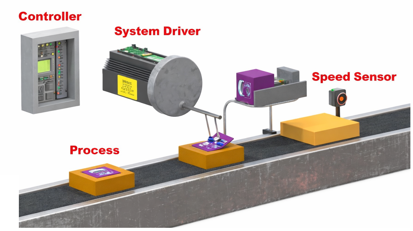
Figure 1. Control System Example
What is a Control System?
A control system is a system that keeps a measured value close to a desired target value. Its purpose is to automatically adjust a process so the output stays correct even when conditions change. For example, a room thermostat keeps temperature near the set level, and a car cruise control keeps the vehicle at a selected speed. A water tank level controller also maintains the water height at a chosen mark. In simple terms, a control system continuously checks and corrects a variable to match the required value.
Basic Elements of a Control System
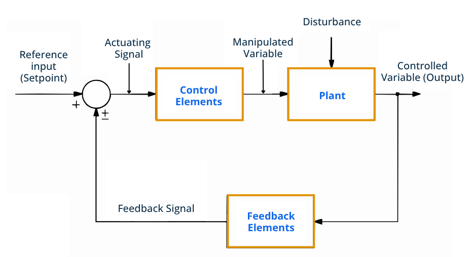
Figure 2. Control System Block Diagram
A control system is made of several standard parts, each performing a specific task.
• Reference Input (Setpoint)
This is the desired value the system tries to maintain. It represents the selected target condition. The system always compares the actual value to this reference.
• Actuating Signal
This is the signal produced after comparing the desired and actual values. It represents how much adjustment is needed. The signal prepares the system for correction.
• Control Elements
These parts handle the decision-making process. They determine the corrective action based on the signal received. The output from this stage prepares the process for adjustment.
• Manipulated Variable
This is the adjustable quantity sent toward the process. Changing this value influences the final output. It is the variable the system can directly vary.
• Plant
The plant is the process being controlled. It produces the final output value. The system aims to keep this output at the desired level.
• Disturbance
This is an unwanted change affecting the process. It can push the output away from the desired value. The system must compensate for it.
• Controlled Variable (Output)
This is the actual measured result of the process. It shows the present condition of the system. The goal is to keep it equal to the reference input.
• Feedback Elements
These measure the output and send information back for checking. They provide the system with the current condition. This allows correction to be determined.
• Feedback Signal
This is the returned information about the output value. It represents the condition of the process. The system uses it for comparison.
Working Principle of the Control System
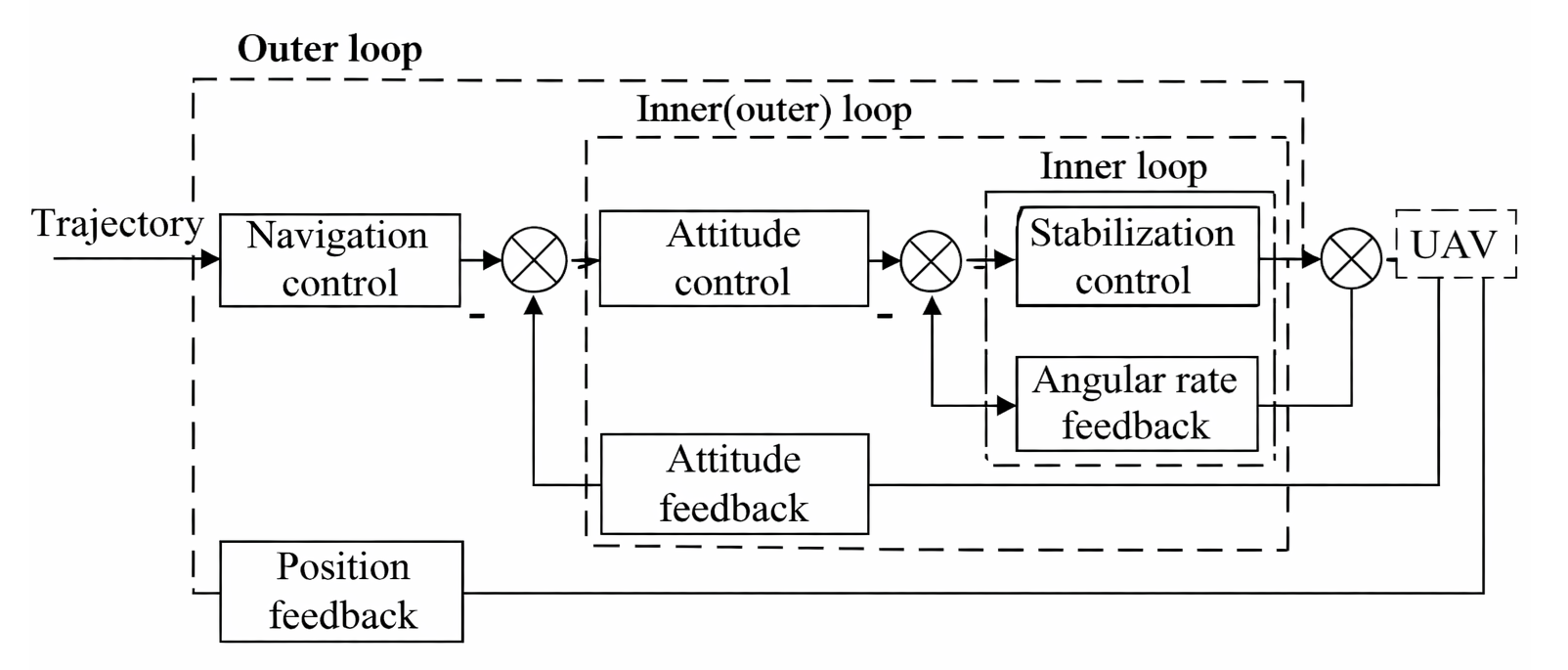
Figure 3. Working Principle of the Control System
The working principle of a control system begins with a desired input value being given to the system. The system then compares this value with the actual output value. The difference between them is called the error signal. If the error exists, the system generates a correction signal. This correction adjusts the process to reduce the error. The output changes and is checked again continuously. The cycle repeats until the output closely matches the desired value.
Characteristics of Control Systems
Control systems are evaluated based on how well they perform during operation. These characteristics describe the quality and reliability of the system response.
|
Characteristics |
Description |
|
Stability |
Output does
not diverge; returns to steady value after disturbance |
|
Accuracy |
Final error ≤
±2–5% of set value |
|
Precision |
Output
variation ≤ ±1% under same input |
|
Response Time |
Initial
reaction occurs within measured delay time (td) |
|
Rise Time |
Time from 10%
to 90% of final value |
|
Settling Time |
Enters and
stays within ±2% band |
|
Overshoot |
Peak exceeds
final value by % amount |
|
Steady-State
Error |
Constant
offset remaining after stabilization |
|
Sensitivity |
ΔOutput /
ΔParameter change ratio |
|
Robustness |
Maintains
operation despite disturbance change |
|
Bandwidth |
Operates
effectively up to −3 dB cutoff frequency |
|
Repeatability |
Same input
produces same output within tolerance |
|
Reliability |
Operates
without failure for rated operating time (MTBF) |
|
Damping |
Oscillation
decay determined by damping ratio ζ |
|
Speed of
Response |
Total time to
reach stable condition |
Types of Control Systems
Control systems are classified based on how they handle information, signals, and response behavior. They are grouped according to feedback usage, signal form, and mathematical behavior.
Open-Loop Control System
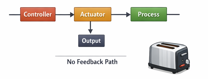
Figure 4. Open-Loop Control System Diagram
An open-loop control system is a system where the output does not influence the control action. The system sends a command and assumes the result is correct without checking it. Because there is no feedback path, it cannot automatically correct errors or disturbances. The performance depends mainly on proper calibration and operating conditions. These systems are simple, low-cost, and easy to design. However, changes in load or environment can affect the final result. Common examples include an electric toaster timer, washing machine timer control, and fixed irrigation timer.
Closed-Loop Control System
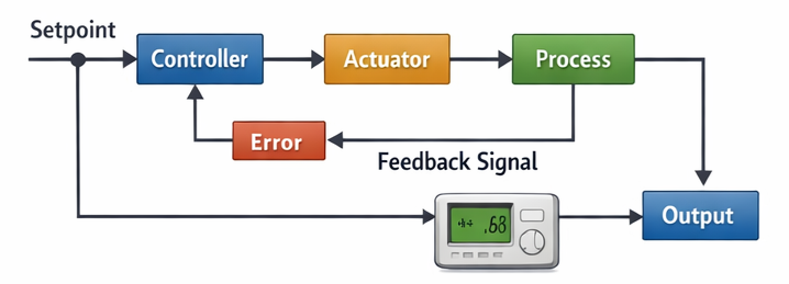
Figure 5. Closed-Loop Control System Diagram
A closed-loop control system is a system that uses feedback to adjust its output automatically. The system measures the result and compares it with the desired value. If a difference appears, a correction is applied to reduce the error. This continuous adjustment allows accurate and stable operation even when conditions vary. Closed-loop systems provide better precision and reliability than open-loop systems. They are widely used in modern automatic control applications. Typical examples include air conditioner temperature control, vehicle cruise control, and automatic voltage regulators.
Continuous-Time Control System
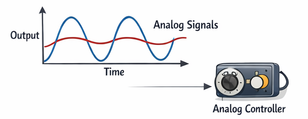
Figure 6. Continuous-Time (Analog) Control Signal
A continuous-time control system processes signals that change smoothly over time. The input and output exist at every instant without interruption. These systems usually work with analog electrical or mechanical signals. Because the signals are continuous, the response is also smooth and natural. Continuous-time systems are commonly found in traditional analog controllers. They are suitable for physical processes requiring immediate reaction. Examples include analog speed regulators, audio amplifier volume control, and hydraulic valve position control.
Discrete-Time Control System
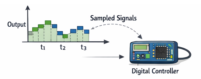
Figure 7. Discrete-Time (Digital) Control Signal
A discrete-time control system operates using sampled data signals. The system checks and updates values only at specific time intervals. These signals are usually processed by digital controllers or microprocessors. The output changes step by step rather than continuously. Such systems allow programmable operation and flexible adjustment. They are widely used in modern electronic and computer-based control. Examples include microcontroller-based temperature control, digital motor speed control, and smart home thermostats.
Linear Control System
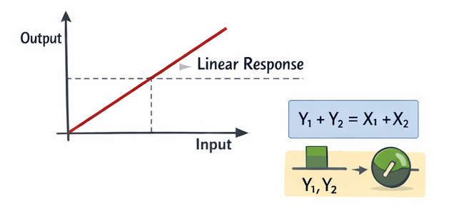
Figure 8. Linear System Input-Output Relationship
A linear control system follows a proportional relationship between input and output. If the input doubles, the output also doubles under the same conditions. These systems satisfy the superposition principle where combined inputs produce combined outputs. Linear behavior allows predictable and easy mathematical analysis. Most theoretical control designs assume linear operation for simplicity. Linear models help in designing stable and accurate systems. Examples include small-signal electronic amplifiers and low-load motor control regions.
Nonlinear Control System
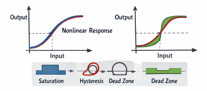
Figure 9. Nonlinear System Response Characteristics
A nonlinear control system has an output that is not proportional to the input. The response changes depending on operating range or conditions. Small input changes may produce large output variations or no change at all. Effects such as saturation, hysteresis, and dead zones often appear. These systems are harder to analyze but represent physical processes more accurately. Many systems naturally behave in a nonlinear way. Examples include robotic arm motion limits, magnetic actuator behavior, and valve flow control at extreme positions.
Advantages and Disadvantages of Control Systems
Control systems improve consistency and reduce manual effort but also introduce complexity and cost.
Advantages of Control Systems
• The system keeps the output close to the required value during operation.
• Operators do not need to keep adjusting the equipment by hand.
• Machines can run for long hours without frequent stopping.
• The system corrects changes in conditions automatically.
• Operation status can be checked from a panel or remote display.
Disadvantages of Control Systems
• Setup cost is higher than simple manual systems.
• Skilled workers are needed for setup and service.
• Sensors and electronic parts can fail over time.
• Finding the cause of problems may take longer.
• The system depends on stable electrical power.
Applications of Control Systems
Control systems are used in both industrial automation and everyday equipment to maintain proper operation automatically.
1. Industrial Manufacturing
Production machines maintain consistent product dimensions and quality. Automated assembly lines use regulation to ensure repeatability. This reduces waste and improves efficiency.
2. Temperature Regulation
Heating and cooling equipment maintains comfortable environmental conditions. Buildings rely on automatic adjustment to stabilize indoor climate. This improves energy efficiency and comfort.
3. Transportation Systems
Vehicles use speed and stability control for smoother operation. Modern cars include cruise control and traction systems. These improve driving safety and performance.
4. Power Systems
Electrical networks regulate voltage and frequency levels. Generators adjust output to match load demand. This ensures stable electricity supply.
5. Robotics and Automation
Robots perform accurate positioning and motion tasks. Automated machines operate continuously with high precision. This enables advanced manufacturing.
6. Medical Equipment
Devices maintain controlled operating conditions during treatment. Monitoring equipment keeps values within safe limits. This improves patient safety and reliability.
7. Home Appliances
Everyday devices automatically manage operation settings. Washing machines and refrigerators maintain proper operation conditions. This simplifies daily tasks.
8. Aerospace Systems
Aircraft and drones maintain stable flight conditions. Automatic guidance keeps correct orientation and altitude. This supports reliable navigation.
Control System vs Automation vs Embedded Systems
These technologies are closely related but serve different engineering purposes within modern electronic and industrial products.
|
Feature |
Control
System |
Automation |
Embedded
System |
|
Main Focus |
Regulation of
variables |
Process
execution |
Device
operation |
|
Purpose |
Maintain
desired value |
Perform tasks
automatically |
Run dedicated
functions |
|
Scope |
Specific
process behavior |
Entire
workflow |
Single
product device |
|
Decision
Capability |
Based on
measured values |
Based on
programmed logic |
Based on
firmware |
|
Feedback Use |
Often
required |
Optional |
Optional |
|
Hardware Type |
Sensors and
actuators |
Machines and
controllers |
Microcontroller
board |
|
Software Role |
Calculation
and correction |
Sequencing
and coordination |
Device
control logic |
|
Response Type |
Continuous
adjustment |
Task
execution |
Functional operation |
|
System Size |
Small to
medium |
Medium to
large |
Very small |
|
Flexibility |
Moderate |
High |
Limited |
|
Time
Requirement |
High |
Moderate |
High |
|
Application
Level |
Process level |
Plant level |
Product level |
|
Example |
Temperature
control |
Factory
production line |
Smart watch |
|
Integration |
Part of
automation |
Contains
control systems |
Supports both |
Conclusion
Control systems maintain stability by continuously comparing actual output with a target value and correcting any error. Their performance depends on core elements like feedback, controller action, and the controlled process. Different classifications define how signals are handled and how accurately a system responds to disturbances. Because of these capabilities, control systems are widely applied in industry, transportation, energy, medical devices, and everyday equipment.
About us
ALLELCO LIMITED
Read more
Quick inquiry
Please send an inquiry, we will respond immediately.
Frequently Asked Questions [FAQ]
1. What is the difference between a controller and a control system?
A controller is only the decision-making device (like a PLC or PID controller). A control system includes the controller plus sensors, actuators, and the process being regulated.
2. What is PID control and why is it important?
PID control uses proportional, integral, and derivative actions to minimize error quickly and smoothly. It improves stability, accuracy, and response speed in most industrial systems.
3. Why do control systems sometimes oscillate or hunt?
Oscillation occurs when corrections are too aggressive or delayed. Poor tuning, slow sensors, or excessive gain cause the output to overshoot repeatedly.
4. What is actuator saturation?
Actuator saturation happens when the actuator reaches its physical limit and cannot increase output further. This prevents the system from correcting large errors.
5. How do control systems handle delays in processes?
They use tuning methods, filters, or predictive algorithms to compensate for lag so the correction happens at the right time.
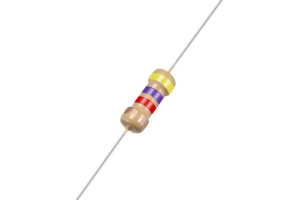
4.7 kΩ Resistor Guide: Color Code, Uses, Testing & Value Comparison
on February 16th
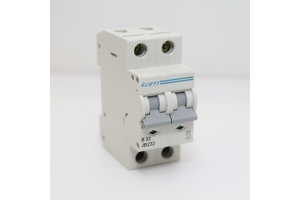
Miniature Circuit Breaker (MCB): Working Principle, Types, Ratings & Selection Guide
on February 15th
Popular Posts
-

Complex Instruction Set Computers: How They Changed Computing?
on April 18th 147749
-

USB-C Pinout and Features
on April 18th 111904
-

Using Xilinx Unified Simulation Primitives: A Comprehensive Guide to FPGA Design and Simulation
on April 18th 111349
-

Power Supply Voltages in Electronics: Meaning of VCC, VDD, VEE, VSS, and GND
on April 18th 83714
-

RJ45 Connector Guide: Pinout, Wiring, Cable Types, and Uses
on January 1th 79502
-

The Ultimate Guide to Wire Color Codes in Modern Electrical Systems
The way our electrical systems use colors isn’t just for looks. Each wire color now indicates a specific function, making it easier to identify and handle electrical components correctly during ins...on January 1th 66869
-

Quality (Q) Factor: Equations and Applications
The quality factor, or 'Q', is important when checking how well inductors and resonators work in electronic systems that use radio frequencies (RF). 'Q' measures how well a circuit minimizes energy...on January 1th 63004
-

Purge Valve Guide: Function, Symptoms, Testing, and Replacement for Optimal Engine Performance
The purge valve is a key part of a car’s system that helps keep the air clean by managing fuel vapors before they can escape into the atmosphere. This not only helps the environment by reducing pol...on January 1th 62943
-

Achieving Peak Performance with the Maximum Power Transfer Theorem
The Maximum Power Transfer Theorem explains how energy from a source, such as a battery or generator, flows to a connected load. It shows the exact condition where the load receives the most power....on January 1th 54076
-

A23 Battery Specifications and Compatibility
The A23 battery is a small, cylinder-shaped battery with high voltage. Also called 23A, 23AE, or MN21, it runs at 12 volts and much higher than AA or AAA batteries. Its special design make...on January 1th 52088
HOT Part Number
-
LTC4063EDD#TRPBF
Analog Devices Inc.
IC BATT CHG LI-ION 1CELL 10DFN
MIMX8MM1CVTKZAA
NXP USA Inc.
IC MPU I.MX 8M MINI SOLOLITE
APDS-9005-020
Broadcom Limited
SENSOR OPT 500NM AMB 6CHIPLED
06031A820KAT2A
KYOCERA AVX
CAP CER 82PF 100V C0G/NP0 0603
ICM-20602
TDK InvenSense
IMU ACCEL/GYRO/TEMP I2C/SPI LGA
170M4611
Eaton - Bussmann Electrical Division
FUSE SQUARE 350A 700VAC RECT
08053C105JAZ2A
KYOCERA AVX
CAP CER 1UF 25V X7R 0805
EP1C12F324C6N
Intel
IC FPGA 249 I/O 324FBGA
2SC4617T1G
onsemi
TRANS NPN 50V 0.1A SC75 SOT416
TL431AILPRAG
onsemi
IC VREF SHUNT ADJ 1% TO92-3
ADAU1787BCBZRL
Analog Devices Inc.
4 ADC, 2 DAC LOW POWER CODEC, AU
74VHC164MTCX
onsemi
IC SHIFT REGISTER 8BIT 14TSSOP
DAN222M3T5G
onsemi
DIODE ARRAY GP 80V 100MA SOT723
NR3015T470M
Taiyo Yuden
FIXED IND 47UH 300MA 1.608OHM SM
MM3Z18VC
onsemi
DIODE ZENER 18V 200MW SOD323F
1N4001W
Rectron USA
DIODE GEN 1A 50V SOD-123F
SMBJ90A
Taiwan Semiconductor Corporation
TVS DIODE 90VWM 146VC DO214AA
NTA1215MC
Murata Power Solutions Inc.
DC DC CONVERTER +/-15V 1W -
SDR1307-101KL
Bourns Inc.
FIXED IND 100UH 1.9A 180MOHM SMD
AOT5B65M1
Alpha & Omega Semiconductor Inc.
IGBT 650V 5A TO220
STP16CP596B1R
STMicroelectronics
IC LED DRIVER LINEAR 50MA 24DIP
AD7895ANZ-2
Analog Devices Inc.
IC ADC 12BIT SAR 8DIP
MURB1620CTT4G
onsemi
DIODE ARRAY GP 200V 8A D2PAK
STGIPS30C60T-H
STMicroelectronics
MOD IPM SLLIMM 30A 600V 25SDIP
IXDN604SIA
IXYS Integrated Circuits Division
IC GATE DRVR LOW-SIDE 8SOIC
CY7C63743-SC
Infineon Technologies
IC MCU 8K LS USB/PS-2 24-SOIC
U2745B-MFBG3
Microchip Technology
RF TX IC UHF 310-440MHZ 16LSSOP
DSPIC30F4013T-30I/PT
Microchip Technology
IC MCU 16BIT 48KB FLASH 44TQFP
ADF4106BRUZ-RL
Analog Devices Inc.
IC CLK/FREQ SYNTH 16TSSOP
EL8403IS
Elantec
IC OPAMP GP 4 CIRCUIT 14SOIC
8A35001B-001AJG
Renesas Electronics America Inc
NETWORK TIMING
GRM0337U1HR90BD01D
Murata Electronics
CAP CER 0.9PF 50V U2J 0201
LT1356CS#PBF
Analog Devices Inc.
IC VOLTAGE FEEDBACK 2 CIRC 16SO
AON7280
Alpha & Omega Semiconductor Inc.
MOSFET N-CH 80V 20A/50A 8DFN
IRLI540N
Infineon Technologies
MOSFET N-CH 100V 23A TO220AB FP
VI-J6Z-MZ
Vicor Corporation
VI-J6Z-MZ 300V 2V 5A -
LMH6722MA
Texas Instruments
IC AMP CURRENT FEEDBACK 14SOIC
HZM6.8Z4MWATL-E
Renesas Electronics America Inc
TVS DIODE 3.5VWM 3MPAK
LM4041DIM7-1.2
Texas Instruments
IC VREF SHUNT 1% SC70-5
RT6200GE
Richtek USA Inc.
IC REG BUCK ADJ 600MA SOT23-6
R5F21274SNFP#X6
Renesas Electronics America Inc
IC MCU 16BIT 16KB FLASH 32LQFP
1N5227B
onsemi
DIODE ZENER 3.6V 500MW DO35
12102C472JAT2A
KYOCERA AVX
CAP CER 4700PF 200V X7R 1210
PZTA64
Fairchild Semiconductor
SMALL SIGNAL BIPOLAR TRANSISTOR,
XC1765ELSO8C
AMD
IC PROM SER C-TEMP 3.3V 8-SOIC
XR88C92CJ-F
MaxLinear, Inc.
IC UART FIFO DUAL 44PLCC
RT24C2X202
Bourns, Inc.
TRIMMER 2K OHM 0.75W PC PIN SIDE
DLW31SN900SQ2L
Murata Electronics
CMC 370MA 2LN 90 OHM SMD
LMK432F476ZM-T
Taiyo Yuden
CAP CER 47UF 10V Y5V 1812
MOC207R1VM
onsemi
OPTOISO 2.5KV TRANS W/BASE 8SOIC
GRM0335C1E390JD01D
Murata Electronics
CAP CER 39PF 25V C0G/NP0 0201
SE10PG-M3/84A
Vishay General Semiconductor - Diodes Division
DIODE GEN PURP 400V 1A DO220AA
RABS15M REG
Taiwan Semiconductor Corporation
BRIDGE RECT 1P 1KV 1.5A ABS-L
PI74LPT16245AEX
Diodes Incorporated
IC TXRX NON-INVERT 3.6V 48TSSOP