Nanofarads and Microfarads: Comprehensive Guide to Capacitance and Conversions
Small units like nanofarads (nF) and microfarads (µF) help us measure how capacitors work. Capacitors are parts used in almost all electronic devices to store and control electricity. This article looks into what nanofarads and microfarads are, how they are used in electronics, and how to switch between these units. We will see how these units help make devices work better and more reliably. Also, we’ll learn about common capacitor values and how to calculate the effect of capacitors in circuits that use alternating current (AC), which helps in making sure electronic systems run smoothly.Catalog

What is the Nanofarad (nF)?
The nanofarad (nF) is a small unit of electrical capacitance. It is equal to one billionth of a farad (1 nF = 10⁻⁹ F). This unit is very important in electronics, especially for measuring the capacitance of small components like capacitors. Capacitors help store and release electrical energy, and they are used in almost every electronic device. The nanofarad is part of the International System of Units (SI), which ensures accurate and standard measurements in electrical engineering. Capacitance is the ability of a capacitor to store an electrical charge. Even though a nanofarad is a very small amount, it plays an important role in many electronic circuits. These tiny capacitance values help in fine-tuning electronic signals. Nanofarad capacitors are often used in circuits that need precise control, such as oscillators that create repeating signals, signal processing systems that handle data transmission, and timing circuits that control when electronic actions happen.
In applications, capacitors with nanofarad ratings help electronic devices work better and faster. They respond quickly to changes in electrical signals and store small amounts of charge effectively. These capacitors are useful in radio frequency (RF) circuits, where they help send and receive signals. They are also found in noise suppression systems, which improve signal quality by reducing unwanted electrical interference. Another use is in power supply circuits, where they stabilize voltage and protect sensitive electronic parts from sudden voltage changes. To make electronic design easier, the nanofarad is written as nF in circuit diagrams and technical documents. This abbreviation helps quickly identify the right capacitors for projects. Using the correct capacitor value is important, especially in high-frequency circuits, where even small mistakes can cause problems.
What is the Microfarad (µF)?
The microfarad (µF) is a unit of electrical capacitance. It is equal to one millionth of a farad (1 µF = 10⁻⁶ F). This unit is commonly used to measure the capacitance of larger capacitors. These capacitors help store and release electrical energy in devices such as power supplies, audio systems, and signal filters. Because they can store more charge than smaller capacitors, microfarad capacitors are used in circuits that need stable and reliable performance. In electronics, capacitors with microfarad values play a role in power supply circuits. They help reduce voltage changes and keep the electrical output steady. This is important in devices that require a constant power supply.

Figure 2. Microfarad
In audio systems, microfarad capacitors are used for signal coupling. They allow alternating current (AC) signals to pass through while blocking direct current (DC), which helps maintain clear and undistorted sound. Without these capacitors, unwanted DC signals could damage audio equipment. Microfarad capacitors are also useful in energy storage systems. They help smooth out power delivery by storing and releasing energy when needed. This is helpful in electronic devices that must quickly adjust to changing power demands. From small gadgets to large industrial machines, these capacitors improve efficiency and reliability. By acting as energy buffers, they prevent sudden voltage drops or spikes that could harm sensitive components.
One of the most common types of microfarad capacitors is the electrolytic capacitor. These capacitors are often found in circuits that convert alternating current (AC) to direct current (DC). This conversion is necessary for many electronic devices, as most operate on DC power. Microfarad capacitors in these circuits help ensure a smooth and stable power flow, which is important for the proper functioning of electronic components. They also extend the lifespan of devices by reducing stress on electrical parts. To make identification easier, microfarad capacitors are labeled with their capacitance value, such as 1 µF for one microfarad. This notation helps select the right capacitor for their circuits. Using the correct capacitor value is require to avoid circuit malfunctions or failures. By following standard labeling and understanding the role of microfarad capacitors, you can design and build reliable electronic systems for a wide range of applications.
Farad and Capacitive Measurements
The farad (F) is the official unit of capacitance in the International System of Units (SI). It helps measure how much electrical charge a capacitor can store. The farad is defined using the equation:
![]()
In this formula, C stands for capacitance in farads, Q represents the charge in coulombs, and V is the voltage in volts. A capacitor has a capacitance of one farad if storing a charge of one coulomb causes its voltage to increase by one volt. This means that the farad measures how well a capacitor can hold and release electrical energy. However, one farad is a very large unit, making it impractical for everyday electronics. If a capacitor had a capacitance of one farad, it would be too big to fit into most electronic devices. Instead, use smaller units like microfarads (µF), nanofarads (nF), and picofarads (pF). These smaller units make it easier to design compact and efficient electronic circuits without taking up too much space. Using these subunits, capacitors can be built in different sizes to fit specific needs. Whether in small mobile phones or large power systems, capacitors help smooth out voltage changes, filter unwanted noise, and protect circuits from sudden voltage spikes.
Even though most electronic devices use capacitors with microfarad or nanofarad values, the farad is still important in special applications. One example is supercapacitors, which have very high capacitance values. These supercapacitors are used in electric vehicles, where they provide quick bursts of energy, and in renewable energy systems, where they help stabilize power supply. Because they can charge and discharge quickly, supercapacitors are useful for handling high energy demands efficiently. Understanding the farad and its smaller units helps choose the right capacitors for different electronic designs. By selecting the proper capacitance value, you can ensure that devices work smoothly and reliably. This knowledge is needed for developing better and more efficient electronic systems in various industries.
Nanofarad to Microfarad Conversion Table
Table showing various nanofarad measurements converted to microfarads.
|
Nanofarad (nF) |
Microfarad (µF) |
|
0.01 nF |
0.00001 µF |
|
0.1 nF |
0.0001 µF |
|
1 nF |
0.001 µF |
|
2 nF |
0.002 µF |
|
3 nF |
0.003 µF |
|
4 nF |
0.004 µF |
|
5 nF |
0.005 µF |
|
6 nF |
0.006 µF |
|
7 nF |
0.007 µF |
|
8 nF |
0.008 µF |
|
9 nF |
0.009 µF |
|
10 nF |
0.01 µF |
|
20 nF |
0.02 µF |
|
30 nF |
0.03 µF |
|
40 nF |
0.04 µF |
|
50 nF |
0.05 µF |
|
60 nF |
0.06 µF |
|
70 nF |
0.07 µF |
|
80 nF |
0.08 µF |
|
90 nF |
0.09 µF |
|
100 nF |
0.1 µF |
|
200 nF |
0.2 μF |
|
300 nF |
0.3 μF |
|
400 nF |
0.4 μF |
|
500 nF |
0.5 μF |
|
600 nF |
0.6 μF |
|
700 nF |
0.7 μF |
|
800 nF |
0.8 μF |
|
900 nF |
0.9 μF |
|
1 000 nF |
1 µF |
|
2 000 nF |
2 µF |
|
3 000 nF |
3 µF |
|
4 000 nF |
4 µF |
|
5 000 nF |
5 µF |
|
6 000 nF |
6 µF |
|
7 000 nF |
7 µF |
|
8 000 nF |
8 µF |
|
9 000 nF |
9 µF |
|
10 000 nF |
10 µF |
How to Convert Nanofarads to Microfarads?
Converting capacitance values from nanofarads (nF) to microfarads (µF) is an important task in electronics. It helps to select the right capacitors for circuits, ensuring that components work correctly together. Different measurement units are used to describe capacitance, so understanding how to switch between them is needed when reading circuit diagrams, ordering parts, or replacing capacitors in electronic devices.
Conversion Method
To convert nanofarads to microfarads, you need to remember a simple rule:
![]()
This means that to change a capacitance value from nanofarads to microfarads, you simply divide by 1000. This method ensures accuracy and consistency when working with different capacitor values in various electronic applications. Let’s say you have a capacitor labeled 5000 nF and you need to convert it to microfarads:
![]()
So, 5000 nF is equal to 5 µF. By following this simple division rule, you can quickly convert any nanofarad value into microfarads without confusion. The reason behind this conversion lies in the definitions of metric prefixes used in the International System of Units (SI):
• Micro (µ) means 10⁻⁶ farads (one-millionth of a farad).
• Nano (n) means 10⁻⁹ farads (one-billionth of a farad).
Since one microfarad (1 µF) is equal to 1000 nanofarads (1000 nF), the conversion follows a simple 1000:1 ratio. This makes calculations easy and helps avoid mistakes when switching between different units of capacitance. This conversion is very useful in electronics, especially when reading capacitor values on circuit diagrams or working with different labeling systems. Some manufacturers list capacitance in nanofarads, while others use microfarads. Being able to switch between these units helps prevent errors when choosing components. This knowledge is also needed when replacing capacitors. If a circuit requires 0.47 µF, but the available capacitor is labeled 470 nF, knowing that 470 nF = 0.47 µF allows you to confidently use the correct part. By mastering this simple conversion, you can ensure proper capacitor selection, maintain circuit functionality, and prevent electrical failures in both small electronic gadgets and complex industrial systems.
Capacitance Conversion Formulas
Understanding how to convert capacitance values between different units is very important in electronics. When designing circuits, others often work with capacitors labeled in different units, such as nanofarads (nF) and microfarads (µF). Knowing how to switch between these units helps ensure that the right components are selected and used correctly in electronic systems. Capacitance is a measure of how much electrical charge a capacitor can store. Since capacitors come in many sizes, they are labeled with different unit prefixes to make their values easier to read and use. The ability to convert between nanofarads (nF) and microfarads (µF) is need for designing, analyzing, and troubleshooting electronic circuits.
To change a capacitance value from nanofarads (nF) to microfarads (µF), multiply the number of nanofarads by 0.001. This is because 1 microfarad is equal to 1000 nanofarads. The conversion formula:
![]()
Example, if you have a 2200 nF capacitor and want to convert it to microfarads:
![]()
So, 2200 nF is equal to 2.2 µF.
To convert a capacitance value from microfarads (µF) to nanofarads (nF), multiply the number of microfarads by 1000. Since 1 microfarad contains 1000 nanofarads, this simple multiplication helps in quickly finding the equivalent value. The conversion formula:
![]()
Example, if you have a capacitor with a capacitance of 4.7 µF and want to convert it to nanofarads:
![]()
So, 4.7 µF is equal to 4700 nF.
These simple formulas make it easy to work with different capacitance values. Many circuit diagrams, datasheets, and component labels use different units, so quick and accurate conversions help in choosing the right capacitor when replacing or upgrading components, reading and interpreting circuit diagrams with varying unit notations, ensuring proper circuit functionality with the correct capacitance value, and preventing errors that could lead to malfunctions or inefficiencies. By mastering these conversions, anyone working with electronics can confidently handle capacitors and design circuits that function efficiently and reliably. Whether working on small electronic gadgets or large electrical systems, these simple calculations ensure precision in circuit design and performance.
Applying Conversion Techniques in Practical Scenarios
Converting capacitance values from nanofarads (nF) to microfarads (µF) is a common task in electronics. Many electronic components, particularly capacitors, are labeled with different unit prefixes depending on the manufacturer or region. Some circuit diagrams and technical specifications list capacitance values in microfarads, while others use nanofarads. To ensure that the correct capacitor is used in a circuit, you must be able to convert between these units easily. This ability helps prevent errors, ensures compatibility between components, and allows for smooth circuit functionality. Whether designing a new circuit, troubleshooting an existing one, or replacing capacitors, quick and accurate conversions between nanofarads and microfarads help maintain efficiency and reliability in electronic systems.
One common scenario where capacitance conversion is necessary is when working with larger capacitance values. Suppose you have a capacitor labeled 2000 nanofarads (nF), but your circuit diagram specifies that the required capacitance should be in microfarads (µF). To check if this capacitor is suitable, you must convert its value into microfarads. The formula for converting nF to µF is simple: divide the capacitance in nanofarads by 1000. Applying this formula, we calculate 2000 nF ÷ 1000 = 2 µF. This means that a capacitor with 2000 nF of capacitance is equivalent to 2 µF, and it can be used in any circuit that requires a 2 µF capacitor. This quick conversion allows to verify component specifications and ensure the right capacitor is chosen for the circuit.
Another example involves converting smaller capacitance values from nanofarads to microfarads. Suppose you have a capacitor with a capacitance of 750 nF, but the circuit requires the value to be in µF for compatibility. Using the same conversion formula, we divide 750 nF by 1000, which results in 0.75 µF. This confirms that a capacitor labeled 750 nF is the same as one labeled 0.75 µF. This simple but effective method helps avoid confusion when selecting or replacing capacitors, ensuring that the right values are used to maintain circuit efficiency and stability.
Understanding and applying these conversions is important because capacitance values are often expressed in different units across various technical documents and circuit diagrams. Working with a datasheet that lists capacitor values in nanofarads but the circuit are designing uses microfarads, knowing how to convert between the two ensures that the correct components are selected. This knowledge is useful when ordering capacitors from different suppliers. In cases where a specific capacitor value is unavailable, converting between these units allows for finding a suitable alternative with an equivalent capacitance, preventing delays in circuit assembly or repair. Mastering capacitance conversion techniques, ensure accuracy, compatibility, and reliability of electronic circuits. Converting between nanofarads and microfarads helps in preventing circuit malfunctions, avoiding costly mistakes, and ensuring smooth electronic performance. Whether working on simple electronic gadgets or complex industrial circuits, knowing how to quickly and accurately switch between these units is a valuable skill that enhances efficiency and precision in electronic design and troubleshooting.
Standard Capacitance Values and E-series
In electronics, capacitors come in many different values, but not every possible value is manufactured. Instead, capacitor values follow a standardized system called the E-series. This system helps ensure that capacitors are available in logical and practical values, making it easier to choose the right components for circuits. The E-series arranges values in a way that covers different levels of precision and tolerance, allowing electronic devices to function reliably without requiring an endless variety of component values.
The E-series is a system that organizes component values in a structured way, dividing each decade (a range of values from 1 to 10, 10 to 100, and so on) into a specific number of preferred values. These values are chosen using a logarithmic scale, which means that each step in the series represents a percentage increase from the previous value. The different E-series groups exist to match various levels of tolerance in electronic components. The more values a series has per decade, the tighter the tolerance and the more precise the components.
E3 Series: Contains 3 values per decade and is used for components with a large tolerance of ±40%. These are used in applications where high precision is not required.
E6 Series: Contains 6 values per decade and is used for components with a ±20% tolerance. This series balances cost and precision and is commonly found in electronics.
E12 Series: Contains 12 values per decade and is used for components with a ±10% tolerance. It is preferred for more accurate electronic applications.
E24 Series: Contains 24 values per decade and is designed for components with a ±5% tolerance. It is used in industrial and specialized electronics.
E48 Series: Contains 48 values per decade and supports a ±2% tolerance. It is suitable for high-precision applications, such as communication devices.
E96 Series: Contains 96 values per decade and supports a ±1% tolerance. This series is used in precision electronics where component values must be highly accurate.
E192 Series: Contains 192 values per decade and is used for components with extremely tight tolerances of ±0.5%, ±0.25%, or ±0.1%. These capacitors are great in advanced technology and precision engineering projects.
For example, within the E6 series, the preferred capacitor values include 10, 15, 22, 33, 47, and 68. As the series progresses to E12, E24, and beyond, more specific values are added to allow finer adjustments in circuit designs. This system ensures that you can select the most suitable capacitor value without requiring every possible number, making component selection simpler and more efficient.
Calculating Capacitive Reactance in AC Circuits
Understanding capacitive reactance is important when working with AC circuits. Capacitors do not behave the same way in AC circuits as they do in DC circuits. Instead of simply storing charge, they oppose the flow of alternating current (AC) in a way that depends on the frequency of the signal. This opposition is known as capacitive reactance (XₐₙₐₜₕC). Unlike resistance, which remains constant, capacitive reactance changes depending on the frequency of the AC signal and the capacitance of the capacitor. Learning how to calculate capacitive reactance helps design circuits that function correctly in applications such as signal filtering, impedance matching, and phase shifting. The capacitive reactance of a capacitor in an AC circuit can be calculated using the formula:
![]()
where XC is the capacitive reactance (measured in ohms, Ω), f is the frequency of the AC signal (measured in hertz, Hz), C is the capacitance (measured in farads, F), and π (pi) is a mathematical constant, approximately 3.14159.
This formula demonstrates that capacitive reactance is inversely proportional to both frequency and capacitance. In practical terms, when the frequency increases, the capacitive reactance decreases, allowing more AC to pass through the capacitor. Similarly, when the capacitance increases, the reactance also decreases, meaning the capacitor permits a greater flow of AC. This relationship is important in circuit design, particularly in applications such as filtering, coupling, and impedance matching, where capacitors play a role in controlling signal flow and system performance.
Since most capacitors used in circuits have capacitance values in microfarads (µF) or nanofarads (nF), it is important to convert these values into farads (F) before applying the formula. The conversion rules are:
• 1 µF = 1 × 10⁻⁶ F (one microfarad equals one-millionth of a farad).
• 1 nF = 1 × 10⁻⁹ F (one nanofarad equals one-billionth of a farad).
Before performing calculations, always express the capacitance in farads to ensure accuracy.
Example Calculations: Effects of Frequency and Capacitance
Capacitive Reactance at Different Frequencies
Let's consider a capacitor with a capacitance of 100 nF (0.1 µF or 0.1 × 10⁻⁶ F) and calculate its capacitive reactance at different frequencies:
1. At 50 Hz:
![]()
![]()
2. At 1 kHz (1000 Hz):
![]()
![]()
3. At 10 kHz (10,000 Hz):
![]()
![]()
These results show that as frequency increases, capacitive reactance decreases. This means that at higher frequencies, the capacitor allows more AC to pass through, making it an effective high-pass filter in electronic circuits.
Capacitive Reactance with Different Capacitance Values
Now, let's see how capacitive reactance changes when using different capacitors, keeping the frequency constant at 1 kHz (1000 Hz):
1. For 10 nF (0.01 µF or 0.01 × 10⁻⁶ F):
![]()
![]()
2. For 1 µF (1 × 10⁻⁶ F):
![]()
![]()
3. For 10 µF (10 × 10⁻⁶ F):
![]()
![]()
These calculations show that as capacitance increases, capacitive reactance decreases. This means that larger capacitors allow more AC to flow, which is useful in applications like power supply filtering, where capacitors help smooth out voltage fluctuations.
Impacts on Circuit Performance
Frequency Filters: Capacitors play a role in frequency filtering applications, particularly in designing low-pass and high-pass filters. A high-pass filter allows high-frequency signals to pass while blocking low-frequency signals, making it useful in applications like audio equalization and signal processing. Conversely, a low-pass filter permits low-frequency signals while attenuating higher frequencies in smoothing out signals and reducing noise in power supplies. By carefully selecting the capacitance value, you can fine-tune the cutoff frequency of these filters, controlling which frequencies are allowed or suppressed. This principle is widely applied in audio systems, radios, and communication devices, where precise frequency control is necessary for clear signal transmission and reception.
Impedance Matching: In AC circuits, impedance matching is important for maximizing power transfer and minimizing signal reflection or loss. Mismatched impedance can lead to inefficient energy transfer, signal degradation, and unwanted interference, particularly in high-frequency applications. Capacitors help achieve proper impedance matching by adjusting the reactive component of a circuit’s impedance, ensuring optimal signal flow. This technique is important in radio frequency (RF) circuits and audio electronics, where maintaining consistent signal strength and clarity is required. Properly matched impedance improves the efficiency of antennas, transmission lines, and amplifiers, enhancing overall circuit performance and stability.
Phase Shifting: One of the unique properties of capacitors in AC circuits is their ability to shift the phase of an alternating current signal by 90 degrees. In a purely capacitive circuit, the current leads the voltage by a quarter of a cycle, a behavior that is strategically used in various electronic applications. This phase-shifting property is great in oscillators, where capacitors help generate stable waveforms for clocks and signal processing circuits. It is also utilized in motor control circuits to create the necessary phase difference for starting and running certain types of electric motors. By leveraging capacitors for phase shifting, you can design more efficient signal processing and control systems across a wide range of applications.
Common Mistakes in Nanofarad to Microfarad Conversion
Since capacitors are commonly labeled using different units, understanding the correct way to convert between them ensures accurate circuit design and proper component selection. However, even small mistakes in the conversion process can cause major issues in electronic circuits. Errors in capacitance values can lead to incorrect signal processing, unstable power supply regulation, and even complete circuit failure. To prevent these problems, it is important to be aware of common mistakes made during nF to µF conversions and how to avoid them.
Adherence to the Correct Conversion Factor
One of the most important aspects of converting nF to µF is using the correct conversion factor. The basic rule is:
1µF = 1000nF
This means that to convert nanofarads to microfarads, you must divide by 1000. Similarly, to convert microfarads to nanofarads, you multiply by 1000. A common mistake occurs when an incorrect conversion factor is used. Some people mistakenly divide by 100 or 10,000 instead of 1000, which results in completely wrong capacitance values. For example, if you have 4700 nF and mistakenly divide by 100 instead of 1000, you would get 47 µF instead of the correct 4.7 µF. Such an error can lead to serious mismatches in circuit performance, causing instability or incorrect filtering characteristics.
To avoid this mistake, always double-check the conversion factor before performing calculations. If unsure, refer to standard capacitance conversion tables or use a calculator to verify the result. Developing a habit of mentally estimating the expected answer can also help catch errors. If converting a value like 1000 nF, you should already expect the result to be 1 µF, and any deviation from that should raise a red flag.
Accurate Decimal Placement
Decimal placement is another major source of errors in capacitance conversion. Since nF to µF conversion involves dividing by 1000, you must move the decimal point three places to the left. Incorrect placement of the decimal point can result in completely inaccurate capacitance values. For example, consider converting 5000 nF to microfarads:
5000 nF÷1000=5 µF
If the decimal is misplaced, the result might be incorrectly written as 0.005 µF or 500 µF, both of which are completely wrong. Using such incorrect values in a circuit can cause serious problems, such as timing errors in oscillators, incorrect frequency response in filters, and excessive or insufficient power regulation in power supply circuits. To prevent such errors, always verify your conversion by checking the magnitude of the result. If you are converting a value in the thousands, the result should be in whole numbers or decimals above 1. If you are converting values below 1000 nF, the result should be a decimal below 1 µF. Writing down the conversion formula and carefully positioning the decimal before finalizing the answer can help reduce errors.
Maintaining Unit Consistency
Many errors in circuit calculations occur because of mixing different capacitance units without proper conversion. Sometimes, it mistakenly perform calculations using values in nF and µF interchangeably without converting them to a common unit first. For example, if a circuit requires the total capacitance of two capacitors, one 220 nF and another 0.47 µF, they cannot be added directly unless both are in the same unit. Since 0.47 µF = 470 nF, the total capacitance would be:
220 nF+470 nF=690 nF
If you mistakenly add 220 nF + 0.47 µF directly, assuming 0.47 µF = 0.47 nF, you would get an incorrect result of 220.47 nF, which is completely wrong. Such miscalculations can lead to incorrect component selection, affecting the overall circuit behavior. To prevent these errors, always convert all values to the same unit before performing calculations. When adding or comparing capacitances, choose one consistent unit, either nF or µF, and ensure all values are converted properly before proceeding.
Precision and Rounding Considerations
Capacitor values often require high precision, especially in timing circuits, frequency filters, and high-speed signal applications. Rounding errors can have impact on circuit performance. For example, if you are working with a capacitor labeled 749 nF, it might be tempting to round it to 0.7 µF for simplicity. However, the more accurate conversion is 0.749 µF. The small difference might not matter in low-precision circuits, but in high-frequency applications or precision timing circuits, it could cause noticeable deviations in performance.
Consider a timer circuit using a capacitor with a specific capacitance value to determine frequency. If the capacitor value is rounded incorrectly, the oscillation frequency of the circuit could shift, affecting the timing of signals. Similarly, in radio frequency (RF) applications, even slight rounding errors in capacitor values can alter the signal transmission and reception characteristics, leading to reduced efficiency or interference. To avoid such issues, keep full precision during calculations and round only at the final step if necessary. Use standard capacitor values from the E-series to ensure compatibility with available components. Verify manufacturer specifications to ensure that the actual capacitor value used in the circuit matches the calculated requirement.
Roles of Capacitors in Electronic Circuits
Capacitors playing a wide range of roles that contribute to the proper functioning of electronic devices. These small yet powerful components are designed to store and manage electrical energy, making them important in circuits that require power stability, signal processing, or frequency control. Capacitors are found in nearly every electronic device, from smartphones and computers to televisions and industrial machines. Their ability to charge and discharge electrical energy quickly makes them useful for many different applications, each requiring specific types of capacitors with carefully selected capacitance values. Understanding how capacitors work in different roles is key to designing, maintaining, and troubleshooting electronic circuits.
Energy Storage and Voltage Stabilization
One of the most important functions of capacitors is storing electrical energy and stabilizing voltage levels. In this role, capacitors act like tiny rechargeable batteries, temporarily holding an electrical charge and releasing it when needed. This function is great in power supply circuits, where capacitors help maintain a steady voltage output even when the power source fluctuates or the electrical load changes suddenly.
For example, in computer power supplies, capacitors play a major role in ensuring that the CPU, memory chips, and other sensitive components receive a stable power supply. If the voltage suddenly drops or spikes, capacitors release stored energy to compensate for the fluctuation, preventing the system from crashing or malfunctioning. Similarly, in camera flashes, capacitors store electrical energy and release it in a quick burst to power the flash when the button is pressed. This energy storage function is also important in automotive electronics. Modern cars use many electronic systems, such as GPS, sensors, and infotainment displays, all of which require stable power. Capacitors help ensure that the vehicle’s electrical system runs smoothly, even when there are rapid changes in power demand, such as when the air conditioning or headlights are turned on.

Figure 3. Energy Storage and Voltage Stabilization
Filtering Noise and Smoothing Outputs
Another function of capacitors is filtering out electrical noise and smoothing voltage outputs. Electrical noise is unwanted interference that can distort signals and affect circuit performance. In power supply circuits, capacitors help eliminate fluctuations and voltage spikes that occur when AC (alternating current) is converted into DC (direct current). Without capacitors, the converted DC power might still contain small ripples from the AC voltage, leading to unstable operation in sensitive circuits.
For example, in audio electronics, capacitors are used to filter out noise from power supplies to ensure clear, high-quality sound. Without capacitors, power fluctuations could introduce unwanted humming or buzzing noises in speakers and microphones. Similarly, in medical devices, such as ECG machines and hearing aids, capacitors play a role in keeping power signals clean, ensuring accurate readings and clear sound output. Capacitors also help prevent electromagnetic interference (EMI) and radio frequency interference (RFI), which can come from nearby electrical devices or radio signals. This is important in communication systems, wireless devices, and sensitive instrumentation, where interference can cause data loss or signal degradation.

Figure 4. Filtering Noise and Smoothing Outputs
Signal Coupling and Decoupling
Capacitors are also widely used for signal coupling and decoupling, which helps maintain the integrity of electrical signals as they move through a circuit. Signal coupling allows AC signals to pass between different stages of an amplifier or circuit while blocking DC voltage. This ensures that only the intended signals reach the next stage, preventing unwanted DC bias from interfering with the signal. This is useful in audio and radio circuits, where capacitors help transmit voice, music, and data signals without distortion.
For example, in a microphone preamplifier, a capacitor is placed between the microphone and the amplifier stage to allow only the audio signal (AC) to pass through while blocking any DC component. This prevents unwanted voltage from reaching the amplifier, improving sound clarity and preventing damage to the circuit. On the other hand, signal decoupling involves using capacitors to remove unwanted AC noise from power lines, ensuring that sensitive electronic components receive clean, stable power. In microcontrollers and digital circuits, capacitors are placed near power pins to filter out high-frequency noise that could interfere with data processing. This is important in computers, smartphones, and industrial control systems, where precise voltage regulation is necessary for reliable operation.
Enhancing Signal Integrity in Timing and Oscillator Circuits
Capacitors are use in timing, frequency control, and oscillator circuits, where they work alongside resistors and inductors to set specific time intervals or frequencies. These circuits are used in clocks, signal generators, and communication devices to ensure that electrical signals remain stable and precise. For instance, in oscillator circuits, capacitors and inductors form resonant circuits that generate stable frequency signals. These signals are used in devices such as radios, televisions, and wireless transmitters, where accurate signal timing is great for proper communication. In digital clocks and timers, capacitors control the charge and discharge cycles, determining the time intervals between operations. Another common application is in phase-locked loops (PLLs), which use capacitors to synchronize signals in communication systems. PLLs are used in mobile phones, satellite communications, and GPS systems to ensure that signals are received and processed at the correct timing.
Conclusion
Looking closely at nanofarads and microfarads shows us how important they are in making electronic circuits. They help keep the power stable, manage energy, and make sure signals in devices are clear and correct. This article explained how to change between these units and why doing so accurately is important. It also covered the standard values for capacitors and how to figure out their effects in AC circuits. Understanding these basics helps build and fix electronic systems, ensuring that the devices we rely on every day perform well and without problems. This simple guide is a helpful tool, opening doors to more learning and better innovations in technology.
About us
ALLELCO LIMITED
Read more
Quick inquiry
Please send an inquiry, we will respond immediately.
Frequently Asked Questions [FAQ]
1. How many microfarads is 1 nanofarad?
1 nanofarad (nF) is equal to 0.001 microfarads (μF).
2. How many uF is in a nF?
The conversion from nanofarads to microfarads is straightforward: 1 nF equals 0.001 μF.
3. What is the difference between microfarad and nanofarad?
The microfarad (μF) and nanofarad (nF) are units used to measure capacitance. The main difference is their scale: 1 microfarad equals 1,000 nanofarads. This means microfarads are used for higher capacitance values compared to nanofarads.
4. What size is a 100 nF capacitor?
The physical size of a 100 nF capacitor can vary depending on its voltage rating and the type of capacitor. For example, in practical terms, a typical 100 nF ceramic capacitor might be quite small, around a few millimeters across, suitable for surface mount on PCBs. In contrast, a 100 nF film capacitor might be larger, possibly a centimeter or more in length, used where higher voltage ratings are required.
5. Can I replace a capacitor with a higher uF?
Yes, but with caution. Replacing a capacitor with one of a higher microfarad (μF) rating can sometimes work if the circuit can tolerate the increased capacitance, which can affect the timing and performance. However, it's important to ensure that the voltage rating remains the same or higher. Always check the circuit requirements or consult with a technician to avoid malfunction or damage.
6. What is 1 microfarad equal to?
1 microfarad (μF) is equal to 1,000 nanofarads (nF) or 1,000,000 picofarads (pF).

XC3S2000-4FGG676I FPGA: Features, Applications, Specifications and Alternatives
on February 4th
Comprehensive Guide to MAP Sensors: Function, Types, Issues, and Maintenance
on January 31th
Popular Posts
-

Complex Instruction Set Computers: How They Changed Computing?
on April 18th 147749
-

USB-C Pinout and Features
on April 18th 111898
-

Using Xilinx Unified Simulation Primitives: A Comprehensive Guide to FPGA Design and Simulation
on April 18th 111349
-

Power Supply Voltages in Electronics: Meaning of VCC, VDD, VEE, VSS, and GND
on April 18th 83713
-

RJ45 Connector Guide: Pinout, Wiring, Cable Types, and Uses
on January 1th 79502
-

The Ultimate Guide to Wire Color Codes in Modern Electrical Systems
The way our electrical systems use colors isn’t just for looks. Each wire color now indicates a specific function, making it easier to identify and handle electrical components correctly during ins...on January 1th 66866
-

Quality (Q) Factor: Equations and Applications
The quality factor, or 'Q', is important when checking how well inductors and resonators work in electronic systems that use radio frequencies (RF). 'Q' measures how well a circuit minimizes energy...on January 1th 63004
-

Purge Valve Guide: Function, Symptoms, Testing, and Replacement for Optimal Engine Performance
The purge valve is a key part of a car’s system that helps keep the air clean by managing fuel vapors before they can escape into the atmosphere. This not only helps the environment by reducing pol...on January 1th 62934
-

Achieving Peak Performance with the Maximum Power Transfer Theorem
The Maximum Power Transfer Theorem explains how energy from a source, such as a battery or generator, flows to a connected load. It shows the exact condition where the load receives the most power....on January 1th 54074
-

A23 Battery Specifications and Compatibility
The A23 battery is a small, cylinder-shaped battery with high voltage. Also called 23A, 23AE, or MN21, it runs at 12 volts and much higher than AA or AAA batteries. Its special design make...on January 1th 52087
HOT Part Number
-

XC3S50A-4VQG100C
AMD
IC FPGA 68 I/O 100VQFP
SI1102-A-GM
Silicon Labs
SENSOR OPT REFLECTIVE 50CM 8WDFN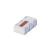
TCN4-13+
Mini-Circuits
1:4 LTCC TRANSFORMER, 650 - 1250
VF30100S-E3/4W
Vishay General Semiconductor - Diodes Division
DIODE SCHOTTKY 100V 30A ITO220AB
GRM033R70J103KA01D
Murata Electronics
CAP CER 10000PF 6.3V X7R 0201
QMK212B7102MDHT
Taiyo Yuden
CAP CER 1000PF 250V X7R 0805
M82351G-12
MACOM Technology Solutions
ACCESS VOICE PROCESSOR
74LV132D,112
Nexperia USA Inc.
IC GATE NAND SCHMIT 4CH 2IN 14SO
AH1801-FJG-7
Diodes Incorporated
MAG SWITCH OMNIPOLAR DFN2020B-3
DG412DY-T1-E3
Vishay Siliconix
IC SWITCH SPST-NOX4 35OHM 16SOIC
PIC16F876A-I/SO
Microchip Technology
IC MCU 8BIT 14KB FLASH 28SOIC
LXA08FP600
Power Integrations
DIODE GP 600V 8A TO220 FULL PACK
FM25V20A-DG
Infineon Technologies
IC FRAM 2MBIT SPI 40MHZ 8DFN
CY7C1011CV33-10ZXC
Cypress Semiconductor Corp
IC SRAM 2MBIT PARALLEL 32TSOP II
04023C221KAT2A
KYOCERA AVX
CAP CER 220PF 25V X7R 0402
RO3101A
Murata Electronics
SAW RES 433.9200MHZ SMD
XRD9818ACGTR
MaxLinear, Inc.
IC AFE 3 CHAN 16BIT 28TSSOP
CL21F104ZBANNNC
Samsung Electro-Mechanics
CAP CER 0.1UF 50V Y5V 0805 -

BZT52-B16_R1_00001
Panjit International Inc.
SOD-123, ZENER
P0300ECL
Littelfuse Inc.
THYRISTOR 25V 400A TO226-2
TPS73615DBVTG4
Texas Instruments
IC REG LINEAR 1.5V 400MA SOT23-5
SN74AXC4T774BQBR
Texas Instruments
IC TRANSCEIVER HALF 4/4 16WQFN
170M5954
Eaton - Bussmann Electrical Division
FUSE SQUARE 350A 1KVAC RECT
CC0805KRX7R9BB682
YAGEO
CAP CER 6800PF 50V X7R 0805
SRP7028A-6R8M
Bourns Inc.
FIXED IND 6.8UH 4.5A 60 MOHM SMD
SMAJ150CA
Taiwan Semiconductor Corporation
TVS DIODE 150VWM 243VC DO214AC
PE-68675
Pulse Electronics
IC CHIP
MAX14890EATJ+
Analog Devices Inc./Maxim Integrated
IC RECEIVER 0/4 32TQFN
TFZGTR20B
Rohm Semiconductor
DIODE ZENER 20V 500MW TUMD2
1N5406-E3/73
Vishay General Semiconductor - Diodes Division
DIODE GEN PURP 600V 3A DO201AD
ME501610
Powerex Inc.
BRIDGE RECT 3P 1.6KV 100A MODULE
GRM1555C2A5R8DA01D
Murata Electronics
CAP CER 5.8PF 100V C0G/NP0 0402
MRF8S19140HSR3
NXP USA Inc.
FET RF 65V 1.96GHZ NI780HS
TN2130K1-G
Microchip Technology
MOSFET N-CH 300V 85MA TO236AB
ADL5519ACPZ-R7
Analog Devices Inc.
IC AMP LOG DETECT CTRLR 32LFCSP
SP3222ECT-L
MaxLinear, Inc.
IC TRANSCEIVER FULL 2/2 18SOIC -
502AT-2
Semitec USA Corp
NTC THERMISTORS 5KOHM 1%
NFM18CC101R1C3D
Murata Electronics
CAP FEEDTHRU 100PF 20% 16V 0603
PS2562L-1-F3-A
Renesas Electronics America Inc
OPTOISOLATOR 5KV DARL 4SMD
502494-0370
Affinity Medical Technologies - a Molex company
2.0 W/B SGL R/ARECASSY3CKTEMBSTP
C1206C223K5RACTU
KEMET
CAP CER 0.022UF 50V X7R 1206
NIS5102QP2HT1G
onsemi
IC HOT SWAP CTRLR GP 12PLLP
VI-J62-MY
Vicor Corporation
DC DC CONVERTER 15V 50W
ADR441ARMZ-REEL7
Analog Devices Inc.
IC VREF SERIES 0.12% 8MSOP
MIC5200-5.0BS
Microchip Technology
IC REG LINEAR 5V 100MA SOT223-3
TAS3251DKQR
Texas Instruments
IC AMP D MONO/STER 350W 56HSSOP
GRM1886T1H360JD01D
Murata Electronics
CAP CER 36PF 50V T2H 0603
TZM5249B-GS08
Vishay General Semiconductor - Diodes Division
DIODE ZENER 19V 500MW SOD80
LM2575-5.0YWM
Microchip Technology
IC REG BUCK 5V 1A 24SOIC
RT0402BRE075K6L
YAGEO
RES SMD 5.6K OHM 0.1% 1/16W 0402
C0603JB1A104M030BC
TDK Corporation
CAP CER 0.1UF 10V JB 0201
CSD17571Q2
Texas Instruments
MOSFET N-CH 30V 22A 6SON
P4SMA13CA
Bourns Inc.
TVS DIODE 11.1VWM 18.2VC DO214AC
AR0144ATSM20XUEA0-DPBR
onsemi
1MP 1/4 CIS SO