Push Button Switch Explained for Easy Learning
Push button switches let you control electrical circuits easily with a simple press. In this article, you will learn what a push button switch is, how it works, and the main parts inside it. You will also understand the different types based on operation, contact configuration, and pole and throw. In addition, you will see where they are used, how they compare to other switches, and how to choose the right one.Catalog

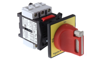
Figure 1. Push Button Switch
What is a Push Button Switch?
A push button switch is a simple electrical device used to manually control a circuit by pressing a button. It is commonly found in control panels, machines, and electronic devices where quick user input is required. This type of switch allows a user to start, stop, or trigger an action with a single press. It is designed for easy operation and reliable performance in both low-power and high-power systems.
Push button switches are widely used because they provide direct and intuitive control. They are often installed on panels or equipment for convenient access. These switches are available in different sizes, shapes, and materials depending on the application. Their main purpose is to provide a fast and efficient way to control electrical functions without complex mechanisms.
Working Principle of Push Button Switch
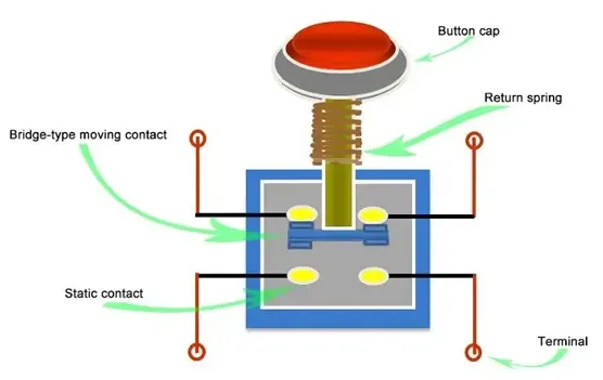
Figure 2. Working Mechanism
A push button switch works by changing the state of an electrical circuit when the button is pressed. When no force is applied, the circuit remains in its default state, either open or closed depending on the design. Pressing the button applies force to an internal mechanism, which causes the electrical contacts to move. This movement either allows current to flow or stops it instantly.
As the button is released, the switch returns to its original state, restoring the circuit to its default condition. This quick transition ensures reliable control of electrical signals in real time. The change in contact position directly affects current flow, making the switch act as a control point in the circuit. This simple action makes push button switches effective for precise and repeated operations.
Components of a Push Button Switch

Figure 3. Push Button Internal Structure
• Button Cap (Actuator)
The button cap is the visible part that press to operate the switch. It is designed for easy contact and can come in different colors and shapes for identification. The actuator transfers the applied force to the internal mechanism. Its design ensures smooth and consistent pressing action over repeated use.
• Return Spring
The return spring is responsible for bringing the button back to its original position after being pressed. It stores mechanical energy when compressed and releases it when the force is removed. This ensures the switch resets quickly and reliably. The spring also helps maintain consistent tactile feedback during operation.
• Moving Contact (Bridge Contact)
The moving contact shifts position when the button is pressed. It connects or disconnects the electrical path inside the switch. This part is designed for durability to handle repeated contact cycles. Its movement directly determines whether current flows through the circuit.
• Static Contact
The static contact remains fixed inside the switch and serves as the connection point for the moving contact. It forms the electrical path when touched by the moving contact. These contacts are usually made of conductive materials for efficient current transfer. Their stable position ensures consistent switching performance.
• Contact Block Assembly
The contact block houses the contact system and supports proper alignment. It ensures that the moving and static contacts meet correctly during operation. This structure helps maintain electrical reliability and reduces wear. It also allows modular replacement in some switch designs.
• Terminals (Electrical Connections)
Terminals are the external connection points where wires are attached. They allow the switch to be integrated into an electrical circuit. These can be screw-type, solder-type, or quick-connect terminals. Proper terminal design ensures secure and stable electrical connections.
• Housing (Body/Base)
The housing encloses all internal components and provides mechanical protection. It is typically made of durable plastic or metal materials. The housing also supports mounting on panels or enclosures. It protects the internal parts from dust, moisture, and mechanical damage.
Types of Push Button Switches
Based on Operation
1. Momentary Push Button Switch
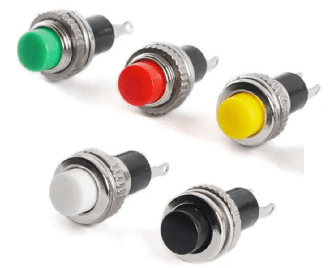
Figure 4. Momentary Switch Example
A momentary push button switch is a type of switch that remains active only while it is being pressed. Once the pressure is removed, it automatically returns to its original state. This behavior is commonly used in applications that require temporary activation, such as doorbells or control signals. The quick return action ensures precise and short-duration control.
These switches are designed to provide immediate response during operation. The pressing action triggers a change, and releasing it stops the action instantly. This makes them suitable for systems where continuous activation is not needed. Their simple operation and fast reset behavior make them widely used in control panels and electronic devices.
2. Latching (Maintained) Push Button Switch
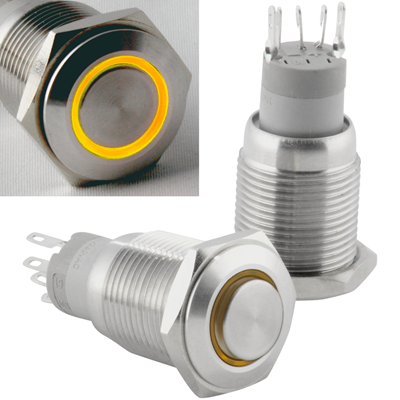
Figure 5. Latching Switch Example
A latching push button switch is a type of switch that stays in its last position after being pressed. When the button is pressed once, it remains activated until it is pressed again to change its state. This allows the switch to maintain its function without continuous pressure. It is commonly used for on/off control in electrical systems.
This type of switch provides stable operation for applications that require a constant state. The user does not need to hold the button to keep the circuit active. Pressing it again toggles the state back, making it easy to control devices. Its maintained behavior is useful in power control and equipment operation.
Based on Contact Configuration

Figure 6. NO vs NC Diagram
1. Normally Open (NO)
A normally open push button switch is a type of switch where the circuit is open in its default state. This means no current flows until the button is pressed. When the button is pressed, the contacts close and allow current to pass through the circuit. Once released, the circuit returns to its open state.
This type of configuration is commonly used in control systems that require activation only when needed. It ensures that the circuit remains inactive unless triggered by the user. The behavior is clearly shown in typical contact diagrams where the gap closes during operation. It is widely used in start buttons and signal inputs.
2. Normally Closed (NC)
A normally closed push button switch is a type of switch where the circuit is closed in its default state. This allows current to flow continuously when the button is not pressed. Pressing the button opens the circuit and interrupts the current flow. Releasing the button restores the closed circuit condition.
This configuration is commonly used in safety systems and emergency stop functions. It ensures that the circuit remains active unless intentionally interrupted. The change in contact state is clearly represented in standard diagrams during operation. It is useful in applications where interruption of current is required for protection.
Based on Pole and Throw

Figure 7. SPST and SPDT Diagram
SPST and SPDT are single-pole switch configurations that control one electrical circuit. An SPST (Single Pole Single Throw) switch has one input and one output, allowing simple on/off control. It acts as a basic switch that either connects or disconnects a circuit. This makes it suitable for straightforward switching tasks.
An SPDT (Single Pole Double Throw) switch also controls one circuit but provides two possible output paths. It allows the current to be directed to one of two connections. This makes it useful for selecting between two different circuits or modes. The diagram typically shows one input switching between two outputs.
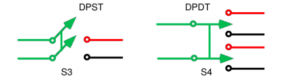
Figure 8. DPST and DPDT Diagram
DPST and DPDT are double-pole switch configurations designed to control multiple circuits at the same time. A DPST (Double Pole Single Throw) switch can control two separate circuits simultaneously with a single action. It allows both circuits to be turned on or off together. This is useful in applications requiring synchronized control.
A DPDT (Double Pole Double Throw) switch controls two circuits and provides two switching paths for each. It allows more complex switching by redirecting current in multiple ways. This configuration is commonly used in reversing circuits and advanced control systems. The diagram typically shows two poles switching between two sets of outputs.
Advantages and Disadvantages of Push Button Switches
Advantages of Push Button Switches
• Simple and easy to operate
• Fast response time
• Compact and space-saving design
• Reliable for repeated use
• Available in many sizes and styles
• Suitable for both low and high power systems
Limitations of Push Button Switches
• Limited control compared to complex switches
• Mechanical wear over time
• Requires physical interaction
• May need protection in harsh environments
• Not ideal for continuous switching without support circuits
Applications of Push Button Switches
1. Industrial Control Panels
Push button switches are commonly used in industrial machines for start, stop, and reset functions. They provide quick and direct control for operators handling equipment. Their clear labeling and color coding improve safety and efficiency. These switches are good for reliable machine operation.
2. Consumer Electronics
Many everyday devices such as appliances and gadgets use push button switches for user input. They allow to control functions easily without complex interfaces. Their compact size makes them suitable for small electronic devices. They improve usability and convenience.
3. Automotive Systems
Push buttons are used in vehicles for functions like engine start, horn activation, and control systems. They provide quick access to essential operations while driving. Their durability ensures reliable performance in different conditions. These switches enhance driver control and comfort.
4. Medical Equipment
Medical devices use push button switches for precise and controlled operations. They allow to operate equipment safely and efficiently. Their responsive action is important in different situations. Clean and sealed designs are often used for hygiene.
5. Home Automation Systems
Push buttons are used in smart home systems for lighting, security, and device control. They provide a simple interface for controlling automated features. Their integration with electronic systems makes them versatile. They improve convenience in modern homes.
6. Control and Instrumentation Systems
In measurement and control systems, push buttons are used to trigger functions and adjust settings. They provide accurate manual input for system control. Their reliability ensures consistent performance in sensitive applications. These switches are widely used in testing and monitoring setups.
Push Button Switch vs Toggle Switch vs Rocker Switch
|
Feature |
Push Button
Switch |
Toggle Switch |
Rocker Switch |
|
Actuation Force |
1.5–5 N typical |
2–6 N typical |
2–5 N typical |
|
Travel Distance |
0.5–3 mm |
2–6 mm |
1.5–4 mm |
|
Operation Type |
Momentary or
latching |
Maintained only |
Maintained only |
|
Electrical Life |
100,000–1,000,000
cycles |
50,000–200,000
cycles |
50,000–150,000
cycles |
|
Mechanical Life |
Up to 1,000,000+
presses |
100,000–500,000
toggles |
100,000–300,000
presses |
|
Contact Ratings |
0.1A–10A (low to
medium) |
3A–20A (medium
to high) |
6A–20A (medium
to high) |
|
Mounting Hole
Size |
8mm, 12mm, 16mm,
22mm |
6mm–12mm typical |
20mm–30mm
rectangular cutout |
|
Panel Thickness |
1–6 mm |
1–5 mm |
1–4 mm |
|
Switching Speed |
<10 ms
response |
10–20 ms |
10–20 ms |
|
Contact
Resistance |
≤50 mΩ typical |
≤20 mΩ typical |
≤20 mΩ typical |
|
Sealing Rating |
Up to IP67/IP68
available |
Typically
IP40–IP65 |
Typically
IP40–IP65 |
|
Illumination
Option |
Common (LED
ring/indicator) |
Limited |
Common (backlit
types) |
|
Terminal Types |
Solder, screw,
quick-connect |
Solder, screw |
Quick-connect,
blade |
|
Operating Temperature |
-25°C to +85°C
typical |
-20°C to +85°C |
-20°C to +85°C |
Conclusion
Push button switches offer a reliable and easy way to control electrical circuits through simple manual input. Their operation is based on basic contact movement, supported by well-defined internal components and various configurations such as momentary, latching, NO/NC, and different pole and throw types. They are widely used across industries due to their fast response, compact design, and versatility, despite some limitations like mechanical wear. Choosing the right switch depends on electrical ratings, operation type, environment, and build quality to ensure proper performance and long-term reliability.
About us
ALLELCO LIMITED
Read more
Quick inquiry
Please send an inquiry, we will respond immediately.
Frequently Asked Questions [FAQ]
1. What is the typical lifespan of a push button switch?
Most push button switches last between 100,000 to 1 million cycles, depending on quality and usage conditions. Industrial-grade switches can last even longer with proper maintenance.
2. Can push button switches handle high voltage applications?
Yes, but only if the switch is specifically rated for high voltage and current. Always check the electrical rating to avoid overheating or failure.
3. What is the difference between illuminated and non-illuminated push button switches?
Illuminated switches include built-in LEDs for visibility in low light conditions. Non-illuminated switches do not provide visual feedback.
4. Can push button switches be used in low-voltage electronics like Arduino projects?
Yes, they are commonly used in low-voltage circuits such as Arduino and microcontroller projects. They are ideal for user input and signal triggering.
5. What standards or certifications should a push button switch have?
Look for certifications like CE, UL, or RoHS compliance. These ensure the switch meets safety, environmental, and performance standards.
Electrical Isolator: Working Principle, Types and Applications
on March 30th

Heat Exchanger: Working Principles, Types and Applications
on March 30th
Popular Posts
-

Complex Instruction Set Computers: How They Changed Computing?
on April 17th 147718
-

USB-C Pinout and Features
on April 17th 111769
-

Using Xilinx Unified Simulation Primitives: A Comprehensive Guide to FPGA Design and Simulation
on April 17th 111327
-

Power Supply Voltages in Electronics: Meaning of VCC, VDD, VEE, VSS, and GND
on April 17th 83645
-

RJ45 Connector Guide: Pinout, Wiring, Cable Types, and Uses
on January 1th 79317
-

The Ultimate Guide to Wire Color Codes in Modern Electrical Systems
The way our electrical systems use colors isn’t just for looks. Each wire color now indicates a specific function, making it easier to identify and handle electrical components correctly during ins...on January 1th 66798
-

Quality (Q) Factor: Equations and Applications
The quality factor, or 'Q', is important when checking how well inductors and resonators work in electronic systems that use radio frequencies (RF). 'Q' measures how well a circuit minimizes energy...on January 1th 62963
-

Purge Valve Guide: Function, Symptoms, Testing, and Replacement for Optimal Engine Performance
The purge valve is a key part of a car’s system that helps keep the air clean by managing fuel vapors before they can escape into the atmosphere. This not only helps the environment by reducing pol...on January 1th 62850
-

Achieving Peak Performance with the Maximum Power Transfer Theorem
The Maximum Power Transfer Theorem explains how energy from a source, such as a battery or generator, flows to a connected load. It shows the exact condition where the load receives the most power....on January 1th 54040
-

A23 Battery Specifications and Compatibility
The A23 battery is a small, cylinder-shaped battery with high voltage. Also called 23A, 23AE, or MN21, it runs at 12 volts and much higher than AA or AAA batteries. Its special design make...on January 1th 52023
HOT Part Number
-

BA2903HFVM-CTR
Rohm Semiconductor
IC COMPARATOR 2 GEN PUR 8MSOP
AT45DB041E-SSHN-T
Adesto Technologies
IC FLASH 4MBIT SPI 85MHZ 8SOIC
XC4036XL-1HQ240C
AMD
IC FPGA 193 I/O 240QFP
1812AA122JAT1A\SB
KYOCERA AVX
CAP CER 1200PF 1KV C0G/NP0 1812
LTC6082CGN#TRPBF
Analog Devices Inc.
IC CMOS 4 CIRCUIT 16SSOP
IRU1261CPTR
Infineon Technologies
IC REG PENTIUM 2OUT 516-UTHINPK
IR2131SPBF
Infineon Technologies
IC GATE DRVR HALF-BRIDGE 28SOIC
NCV7344MW3R2G
onsemi
IC TRANSCEIVER HALF 1/1 8DFN
MPC9456FA
NXP USA Inc.
IC CLK BUFFER 1:10 250MHZ 32TQFP
24LC21A-I/SN
Microchip Technology
IC EEPROM 1KBIT I2C 400KHZ 8SOIC
X0202MN 5BA4
STMicroelectronics
SCR 600V 1.25A SOT223
TPS70933DRVT
Texas Instruments
IC REG LINEAR 3.3V 150MA 6WSON
NSS20201LT1G
onsemi
TRANS NPN 20V 2A SOT23-3
MCP41010-I/SN
Microchip Technology
IC DGTL POT 10KOHM 256TAP 8SOIC
SN74HC20NSR
Texas Instruments
IC GATE NAND 2CH 4-INP 14SOP
MAX3031EESE+
Analog Devices Inc./Maxim Integrated
IC DRIVER 4/0 16SOIC
ADP2370ACPZ-R2
Analog Devices Inc.
IC REG BUCK ADJ 800MA 8LFCSP
PS7341L-1B-E3-A
CEL
SSR RELAY SPST-NC 150MA 0-400V -
C1005CH1H681K050BA
TDK Corporation
CAP CER 680PF 50V CH 0402
P0080EC
Littelfuse Inc.
THYRISTOR 6V 400A TO226-2
TLV74125PDBVR
Texas Instruments
IC REG LINEAR 2.5V 150MA SOT23-5
IRFR222
Harris Corporation
N-CHANNEL POWER MOSFET
74ACT541TTR
STMicroelectronics
IC BUF NON-INVERT 5.5V 20TSSOP
B250A-13-F
Diodes Incorporated
DIODE SCHOTTKY 50V 2A SMA
LTC6240IS5#TRPBF
Analog Devices Inc.
IC OPAMP GP 1 CIRCUIT TSOT23-5
LT3973EMSE-3.3#TRPBF
Analog Devices Inc.
IC REG BUCK 3.3V 750MA 10MSOP
SN74LVC2G32DCTRG4
Texas Instruments
IC GATE OR 2CH 2-INP SM8
MAX8874REUK-T
Analog Devices Inc./Maxim Integrated
IC REG LINEAR LDO
KHHD002A5B41Z
ABB Power Electronics Inc.
DC DC CONVERTER 12V 30W
ADR280AKSZ-R2
Analog Devices Inc.
IC VREF SERIES 0.4% SC70-3
GRM0336S1E7R2DD01D
Murata Electronics
CAP CER 7.2PF 25V S2H 0201
AD835ARZ-REEL7
Analog Devices Inc.
IC MULTIPLIER 4-QUADRANT 8-SOIC
M50100THA1600
Sensata-Crydom
DIODE MODULE 1.6KV 100A
FAN3227TMX
Fairchild Semiconductor
FULL BRIDGE BASED PERIPHERAL DRI
CSD17552Q3A
Texas Instruments
MOSFET N-CH 30V 15A/60A 8SON
LQS100A48-1V8REJ
Artesyn Embedded Power
DC DC CONVERTER 1.8V 180W -

1N3341B
Solid State Inc.
DO5 50 WATT ZENER DIODES
TUSB1106RGTR
Texas Instruments
IC TRANSCEIVER HALF 1/1 16QFN
BYM10-1000-E3/97
Vishay General Semiconductor - Diodes Division
DIODE GEN PURP 1KV 1A DO213AB
AH372-W-7
Diodes Incorporated
MAGNETIC SWITCH LATCH SC59-6
04025A1R2BAT2A
KYOCERA AVX
CAP CER 1.2PF 50V NP0 0402
AD976ABR
Analog Devices Inc.
IC ADC 16BIT SAR 28SOIC
MAX44008EDT+T
Analog Devices Inc./Maxim Integrated
IC AMBIENT/PROXIMITY SENS TDFN
A3P400-PQG208
Microchip Technology
IC FPGA 151 I/O 208QFP
MBRB2045CT
SMC Diode Solutions
DIODE ARRAY SCHOTTKY 45V D2PAK
BCR146E6327
Infineon Technologies
BIPOLAR DIGITAL TRANSISTOR
2N3762
Microchip Technology
TRANS PNP 40V 1.5A TO39
SA5534P
Texas Instruments
IC OPAMP GP 1 CIRCUIT 8DIP
04025A331JAT2A
KYOCERA AVX
CAP CER 330PF 50V C0G/NP0 0402
GRT32DR61C226ME01L
Murata Electronics
CAP CER 22UF 16V X5R 1210
MDD250-08N1
IXYS
DIODE MODULE 800V 290A Y2-DCB
06035A8R2BAT2A
KYOCERA AVX
CAP CER 8.2PF 50V C0G/NP0 0603
AO6601
Alpha & Omega Semiconductor Inc.
MOSFET N/P-CH 30V 6-TSOP
TPSMC11AHE3_A/H
Vishay General Semiconductor - Diodes Division
TVS DIODE 9.4VWM 15.6VC DO214AB