Electrical Isolator: Working Principle, Types and Applications
Electrical isolators help you safely disconnect parts of an electrical system from power. In this article, you will learn what an electrical isolator is, why it is important for safety, and how it works under no-load conditions. You will also understand its main components, common types, and how it differs from a circuit breaker. By the end, you will see where isolators are used in electrical systems.Catalog
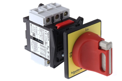
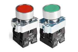
Figure 1. Electrical Isolator
What is an Electrical Isolator?
An electrical isolator is a mechanical switching device used to completely disconnect a part of an electrical circuit from the power supply. Its main purpose is to ensure safe working conditions by providing a clear and visible separation between energized and de-energized sections. Unlike automatic devices, an isolator is operated manually and is designed only for isolation, not for interrupting current. It creates a physical break in the circuit so you can safely perform maintenance or inspection. Electrical isolators are widely used in power systems to improve safety and prevent accidental contact with live components.
Why Electrical Isolators are Important?
Electrical isolators are good for maintaining safety in electrical systems, especially during maintenance and repair work. They ensure that a section of the circuit is completely disconnected, reducing the risk of electric shock or equipment damage. By providing a visible open gap, isolators help confirm that no current is flowing in the isolated part. This makes it safer to work on high-voltage equipment with confidence. Electrical isolators also help prevent accidental energization, which can lead to serious hazards in industrial and power distribution environments.
Electrical Isolator Working Principle
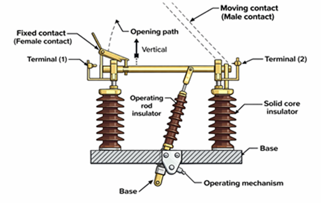
Figure 2. Electrical Isolator Working Diagram
An electrical isolator operates only when there is no load current flowing in the circuit, ensuring safe switching conditions. When the isolator is opened, its moving contact separates from the fixed contact to create a clear air gap. This air gap acts as a visible barrier that confirms electrical disconnection. The opening action is usually performed through a mechanical operating mechanism, allowing smooth and controlled movement. Since there is no current during operation, no arc is produced between the contacts. The isolator remains in the open position to maintain complete isolation until it is manually closed again. This simple operating principle ensures reliable and safe separation of electrical circuits.
Components of an Electrical Isolator
• Fixed Contact
The fixed contact is a stationary conductive part connected to the incoming or outgoing line. It provides a stable point for electrical connection when the isolator is closed. This component is designed to handle high voltage and maintain reliable contact with minimal resistance.
• Moving Contact
The moving contact is the part that physically opens or closes the circuit. It moves away from or toward the fixed contact to create or remove the electrical connection. Its design ensures smooth operation and proper alignment during switching.
• Insulators
Insulators support the conductive parts and prevent unwanted current flow to the ground or structure. They are typically made of porcelain or composite materials for high electrical strength. These components also provide mechanical support to maintain proper spacing between live parts.
• Operating Mechanism
The operating mechanism controls the opening and closing of the isolator. It can be manual or motor-driven depending on the application. This mechanism ensures that the contacts move safely and precisely during operation.
• Base Frame
The base frame holds all components together and provides structural stability. It is usually made of metal to support the mechanical load of the isolator. The frame also ensures proper alignment of contacts and insulators.
Types of Electrical Isolators
Single Break Isolator
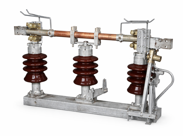
Figure 3. Single Break Isolator
A single break isolator is a type of electrical isolator that uses one contact separation point to disconnect the circuit. It consists of one moving contact that separates from a fixed contact to create a single air gap. This simple structure makes it easy to operate and maintain in standard power systems. The contact movement is usually horizontal or rotational, allowing clear visibility of the open position. Because of its straightforward design, it is commonly used in medium-voltage substations and distribution systems. The equipment shown in the figure reflects its simple contact arrangement and compact layout. Single break isolators are ideal for applications where space and cost efficiency are important.
Double Break Isolator
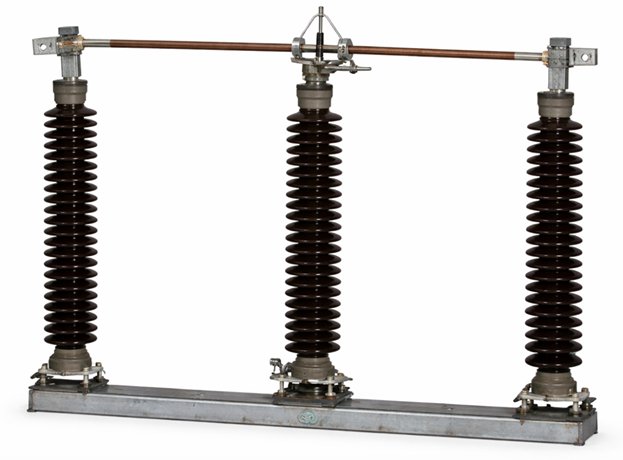
Figure 4. Double Break Isolator
A double break isolator is an electrical isolator that creates two separate contact gaps during operation. It has a central moving contact that separates from two fixed contacts on both sides, forming dual isolation points. This design improves electrical isolation by increasing the distance between live parts. The movement of contacts is balanced, which enhances mechanical stability and performance. It is commonly used in high-voltage substations where stronger insulation is required. The figure illustrates the symmetrical structure that supports efficient disconnection. Double break isolators are suitable for systems that demand higher safety margins and reliable isolation.
Pantograph Isolator
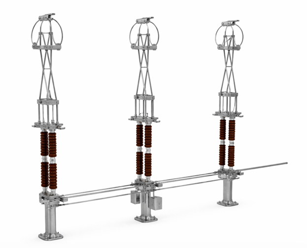
Figure 5. Pantograph Isolator
A pantograph isolator is a type of isolator that uses a vertical lifting mechanism to connect or disconnect the circuit. It features a movable arm that rises upward to make contact with an overhead conductor. This vertical motion allows efficient use of space in compact substations. The structure includes articulated arms that expand and contract during operation. It is widely used in high-voltage applications where horizontal space is limited. The figure shows the distinctive lifting structure that enables vertical switching action. Pantograph isolators are ideal for modern substations requiring compact and flexible layouts.
Horizontal Break Isolator
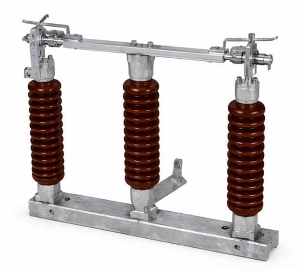
Figure 6. Horizontal Break Isolator
A horizontal break isolator is an electrical isolator in which the moving contact opens sideways to disconnect the circuit. The contacts rotate or swing horizontally to create a visible gap between them. This type is commonly installed in outdoor substations due to its simple structure and ease of maintenance. It provides clear visibility of the open position, which improves operational safety. The design allows easy installation on supporting structures with adequate spacing. The figure reflects the side-opening movement typical of this isolator type. Horizontal break isolators are widely used in transmission and distribution systems.
Vertical Break Isolator
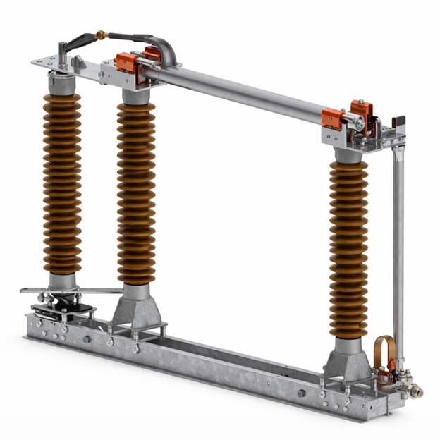
Figure 7. Vertical Break Isolator
A vertical break isolator is an electrical isolator where the moving contact opens upward or downward to create isolation. The vertical motion helps reduce the horizontal space required for installation. This design is useful in substations where space constraints are a concern. The contacts move in a vertical plane, ensuring a clear and visible separation. It is commonly used in high-voltage systems where efficient space utilization is needed. The figure highlights the upward opening mechanism that defines this isolator type. Vertical break isolators are preferred in compact layouts with limited ground area.
Electrical Isolator vs Circuit Breaker
|
Feature |
Electrical
Isolator |
Circuit Breaker |
|
Main Function |
Provides
physical disconnection of a circuit for safety |
Detects faults
and interrupts current to protect the system |
|
Operation Type |
Manual or
motor-operated (non-automatic) |
Automatic
tripping with optional manual control |
|
Load Handling |
Operates only at
0 A (no-load condition) |
Operates under
full load and fault current conditions |
|
Rated
Interrupting Capacity |
0 kA (cannot
interrupt current) |
Typically 6 kA
to 63 kA or higher depending on type |
|
Arc Handling |
No arc
suppression mechanism |
Uses arc
quenching methods (air, oil, SF₆, or vacuum) |
|
Safety Role |
Ensures visible
isolation for maintenance |
Provides
protection against overload and short circuit |
|
Switching Speed |
Slow (seconds,
operator-dependent) |
Fast
(milliseconds, typically 10–100 ms) |
|
Protection
Capability |
No protective
function |
Built-in
protection (overcurrent, short circuit, sometimes earth fault) |
|
Typical Usage |
Maintenance
isolation and safety procedures |
Fault protection
and operational switching |
|
Contact Operation |
Opens only when
current is already zero |
Opens while
current is flowing (including fault current) |
|
Automation Level |
Low (manual or
basic motor control) |
High
(relay-controlled, fully automatic systems) |
|
Installation
Area |
Installed in
substations and switchyards (high-voltage side) |
Used in
substations, distribution panels, and end-user systems |
|
Design
Complexity |
Simple
mechanical structure |
Complex system
with sensing, tripping, and arc control components |
|
Maintenance
Requirement |
Minimal
(inspection and cleaning) |
Regular
maintenance required (contacts, mechanism, arc chamber) |
|
Isolation
Visibility |
Provides visible
air gap (clear disconnection) |
No visible
isolation; requires separate isolator for safety |
Advantages and Disadvantages of Electrical Isolators
Advantages of Electrical Isolators
• Provides a clear visible air gap for safety confirmation
• Highly reliable due to fewer moving parts
• Low maintenance requirements in long-term use
• Cost-effective compared to complex switching devices
• Enhances safety during maintenance procedures
Disadvantages of Electrical Isolators
• Cannot operate under load conditions
• No arc extinguishing mechanism available
• Requires additional devices like circuit breakers
• Manual operation may increase switching time
• Limited functionality compared to protective devices
• Not suitable for fault interruption
Applications of Electrical Isolators
1. Power Substations
Electrical isolators are commonly installed in substations to isolate sections of transmission lines and equipment. They allow safe maintenance by disconnecting high-voltage circuits from the power supply. This helps prevent accidents and ensures reliable system operation.
2. Transmission and Distribution Systems
In power transmission networks, isolators are used to separate faulty or inactive sections. They help maintain system stability by isolating specific lines during repairs. This improves the overall efficiency and safety of power delivery.
3. Industrial Electrical Systems
Industrial plants use isolators to disconnect machinery and electrical panels during servicing. This ensures worker safety when handling electrical equipment. It also helps prevent unexpected machine startup.
4. Switching Stations
Isolators are used in switching stations to control and manage power flow between different network sections. They provide a safe way to isolate circuits without interrupting the entire system. This supports flexible system operation.
5. Renewable Energy Systems
In solar and wind power systems, isolators are used to disconnect panels or turbines from the grid. This allows safe maintenance and inspection of renewable energy equipment. It also protects technicians from electrical hazards.
6. Railway Electrification Systems
Electrical isolators are used in railway systems to isolate overhead lines for maintenance work. They ensure that sections of the track are de-energized before repairs. This improves safety for maintenance crews working on electrified rail networks.
Conclusion
Electrical isolators play a role in electrical safety by providing a clear and reliable way to separate de-energized sections from live circuits. Their value comes from their simple design, visible isolation, and wide use in substations, transmission systems, industrial setups, and other power applications. Different isolator types are designed to suit specific installation and space requirements, while their limitations make them suitable only for no-load switching. Understanding their function, parts, benefits, and uses helps in selecting the right isolator for safe and effective system operation.
About us
ALLELCO LIMITED
Read more
Quick inquiry
Please send an inquiry, we will respond immediately.
Frequently Asked Questions [FAQ]
1. What should I consider when choosing an electrical isolator?
When choosing an electrical isolator, consider voltage rating, current capacity, installation type, and environmental conditions. You should also check compatibility with your system and ensure it meets safety standards for your specific application.
2. Can an electrical isolator be used for both indoor and outdoor applications?
Yes, electrical isolators are available for both indoor and outdoor use. Outdoor isolators are designed with weather-resistant materials and insulation to withstand harsh environmental conditions like rain, dust, and temperature changes.
3. How do I know the correct rating for my electrical isolator?
To select the correct rating, match the isolator’s voltage and current capacity with your system requirements. Always choose a slightly higher rating than your operating conditions to ensure safety and long-term reliability.
4. Is an electrical isolator required by safety standards?
Yes, many electrical safety standards require isolators to ensure safe maintenance and operation. They are good in preventing accidental energization and protecting workers from electrical hazards.
5. How often should an electrical isolator be inspected or maintained?
Electrical isolators should be inspected regularly, typically during scheduled maintenance cycles. Check for contact wear, insulation damage, and mechanical issues to ensure proper operation and safety.
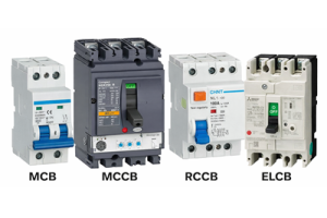
MCB vs MCCB vs RCCB vs ELCB: Complete Comparison Guide
on March 30th
Push Button Switch Explained for Easy Learning
on March 30th
Popular Posts
-

Complex Instruction Set Computers: How They Changed Computing?
on April 16th 147710
-

USB-C Pinout and Features
on April 16th 111641
-

Using Xilinx Unified Simulation Primitives: A Comprehensive Guide to FPGA Design and Simulation
on April 16th 111313
-

Power Supply Voltages in Electronics: Meaning of VCC, VDD, VEE, VSS, and GND
on April 16th 83570
-

RJ45 Connector Guide: Pinout, Wiring, Cable Types, and Uses
on January 1th 79199
-

The Ultimate Guide to Wire Color Codes in Modern Electrical Systems
The way our electrical systems use colors isn’t just for looks. Each wire color now indicates a specific function, making it easier to identify and handle electrical components correctly during ins...on January 1th 66732
-

Quality (Q) Factor: Equations and Applications
The quality factor, or 'Q', is important when checking how well inductors and resonators work in electronic systems that use radio frequencies (RF). 'Q' measures how well a circuit minimizes energy...on January 1th 62918
-

Purge Valve Guide: Function, Symptoms, Testing, and Replacement for Optimal Engine Performance
The purge valve is a key part of a car’s system that helps keep the air clean by managing fuel vapors before they can escape into the atmosphere. This not only helps the environment by reducing pol...on January 1th 62779
-

Achieving Peak Performance with the Maximum Power Transfer Theorem
The Maximum Power Transfer Theorem explains how energy from a source, such as a battery or generator, flows to a connected load. It shows the exact condition where the load receives the most power....on January 1th 54018
-

A23 Battery Specifications and Compatibility
The A23 battery is a small, cylinder-shaped battery with high voltage. Also called 23A, 23AE, or MN21, it runs at 12 volts and much higher than AA or AAA batteries. Its special design make...on January 1th 51927
HOT Part Number
-
C2012X5R2E472M085AA
TDK Corporation
CAP CER 4700PF 250V X5R 0805
HD3SS215ZQER
Texas Instruments
IC DISPLYPRT 2:1 DIFF SW 50BGA
LD59030DTPU28R
STMicroelectronics
IC REG LINEAR 2.8V 300MA 4DFN
LM79L12ACZ
Texas Instruments
IC REG LINEAR FIXED NEG STND
BCM56842A1KFTBLG
Broadcom Limited
MULTI LAYER SWITCH
TPD1E10B09QDPYRQ1
Texas Instruments
TVS DIODE 9VWM 14VC 2X1SON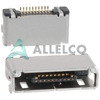
MQ212B-10PR
Hirose Electric Co Ltd
CONN RCPT 10P 0.02 GOLD SMD R/A
GRM0225C1E2R0WDAEL
Murata Electronics
CAP CER 2PF 25V C0G/NP0 01005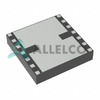
AWB7227RM52P8
Skyworks Solutions Inc.
IC AMP HSDPA 2.11-2.17GHZ 14SMD
Z86E4016FSC
Zilog
IC MCU 8BIT 4KB OTP 44QFP
LD39100PU12RY
STMicroelectronics
IC REG LINEAR 1.2V 1A 6DFN
AD1315KZ
Analog Devices Inc.
HIGH SPEED ACTIVE LOAD
RT0402BRD072K4L
Yageo
RES SMD 2.4K OHM 0.1% 1/16W 0402
ZUS1R52412
Cosel USA, Inc.
DC DC CONVERTER 12V
PN5179
onsemi
RF TRANS NPN 12V 2GHZ TO92-3
VS-20ETS08STRLPBF
Vishay General Semiconductor - Diodes Division
DIODE GEN PURP 800V 20A TO263AB
12105C474J4Z2A
AVX Corporation
CAP CER 0.47UF 50V X7R 1210
2SJ645-E
onsemi
P-CHANNEL SMALL SIGNAL MOSFET -
V300C8H100BN
Vicor Corporation
DC DC CONVERTER 8V 100W
C5750X5R2E684M230KA
TDK Corporation
CAP CER 0.68UF 250V X5R 2220
PFS712EG
Power Integrations
IC PFC CTRLR CCM 95KHZ ESIP-7G
BRT21H
Infineon Technologies
TRIAC OUTPUT OPTOCOUPLER WITH ZE
SMS7630-079LF
Skyworks Solutions Inc.
RF DIODE SCHOTTKY 1V 75MW SC79
LM4050BEM3-5.0
Texas Instruments
IC VREF SHUNT 0.2% SOT23-3
1N5355B
NTE Electronics, Inc
DIODE ZENER 18V 5W AXIAL
SWPA6045S100MT
Shenzhen Sunlord Electronics Co., Ltd.
FIXED IND 10UH 2.45A 62MOHM SMD
IP4058CX8/LF,135
NXP USA Inc.
FILTER RC(PI) ESD SMD
R1190H090D-T1-FE
Nisshinbo Micro Devices Inc.
IC REG LINEAR 9V 1A SOT89-5
HCPL-0631-500E
Broadcom Limited
OPTOISO 3.75KV 2CH OPEN COLL 8SO
UPA2211T1M-T1-AT
Renesas Electronics America Inc
MOSFET P-CH 12V 7.5A 8VSOF
RT0402DRD0712KL
YAGEO
RES SMD 12K OHM 0.5% 1/16W 0402
0603YC392JAT2A
KYOCERA AVX
CAP CER 3900PF 16V X7R 0603
ISL78171ARZ-T7A
Renesas Electronics America Inc
IC LED DRVR RGLTR PWM 50MA 20QFN
RT0402BRE0760R4L
YAGEO
RES SMD 60.4 OHM 0.1% 1/16W 0402
C1005CH2A391J050BA
TDK Corporation
CAP CER 390PF 100V CH 0402
BSS126H6327XTSA2
Infineon Technologies
MOSFET N-CH 600V 21MA SOT23-3 -

GRM0335C2A8R9CA01D
Murata Electronics
CAP CER 8.9PF 100V C0G/NP0 0201
ADSP-TS201SWBP-050
Analog Devices Inc.
IC PROCESSOR 500MHZ 576BGA
AD9748ACPZRL7
Analog Devices Inc.
IC DAC 8BIT A-OUT 32LFCSP
MC13203FC
NXP USA Inc.
IC RF TXRX 802.15.4 32VFQFN
08052U430KAT2A
KYOCERA AVX
CAP CER 43PF 200V NP0 0805
CDBU0230
Comchip Technology
DIODE SCHOTTKY 30V 200MA 0603C
XC6118N33BMR-G
Torex Semiconductor Ltd
IC SUPERVISOR 1 CHANNEL SOT25
V300C12C150BG
Vicor Corporation
DC DC CONVERTER 12V 150W
MIC5219-3.3BMM
Microchip Technology
IC REG LINEAR 3.3V 500MA 8MSOP
SI501-PROG-CAX
Silicon Labs
MEMS OSC PROG BLANK 32KHZ-100MHZ
STM32F051K6U7TR
STMicroelectronics
IC MCU 32BIT 32KB FLASH 32UFQFPN
SN74LV10ADR
Texas Instruments
IC GATE NAND 3CH 3-INP 14SOIC
AC0805JRNPO9BN101
YAGEO
CAP CER 100PF 50V C0G/NPO 0805
FDMS3602S
onsemi
MOSFET 2N-CH 25V 15A/26A POWER56
M2S060TS-FGG484I
Microchip Technology
IC SOC CORTEX-M3 166MHZ 484FBGA
DCW03A-12
MEAN WELL USA Inc.
DC DC CONVERTER +/-12V 3W
MHQ1005P2N2BT000
TDK Corporation
FIXED IND 2.2NH 1A 60 MOHM SMD
ISL6561IRZ
Renesas Electronics America Inc
IC REG CTRLR INTEL 4OUT 40QFN