
A Beginner’s Guide to the JRC4558 Operational Amplifier
The JRC4558 is a dual operational amplifier widely used in various electronic circuits. This guide will walk you through its features, pin configuration, and practical applications in a simple and clear way. Whether you're curious about its workings or looking to use it in your projects, this article has you covered.Catalog

Introduction to JRC4558 Operational Amplifier
The JRC4558 is a dual operational amplifier chip designed for a wide range of electronic applications. This chip combines high input resistance with the ability to amplify signals significantly, making it highly efficient in processing input variations. It features two independent, frequency-compensated amplifiers within a single package, carefully optimized to perform well with a variety of voltage levels.
The output signal generated by the JRC4558 is significantly larger than the input signal, enabling it to amplify weak signals effectively. With a straightforward design, it only requires a 5V power supply to operate in electrical circuits. Its simplicity and versatility make it a reliable choice for both professional engineers and hobbyists.
Pin Details and Configuration
The JRC4558 op-amp has an 8-pin configuration, each with a specific role to ensure smooth operation. Understanding these pins will help you connect the IC correctly in your circuits.

• Pin-1 (OUT-A): This pin serves as the output for the first operational amplifier within the chip.
• Pin-2 (Inverting Input-A): This is the inverting input pin for the first operational amplifier. It is used to receive signals that need to be inverted or processed.
• Pin-3 (Non-Inverting Input-A): This pin is the non-inverting input for the first operational amplifier and accepts the direct input signal.
• Pin-4 (Power (-Vs)): This pin is connected to the negative supply terminal or ground to power the IC.
• Pin-5 (Reference): This pin acts as the non-inverting input for the second operational amplifier.
• Pin-6 (Output): This is the inverting input pin for the second operational amplifier, which helps in signal processing.
• Pin-7 (Power (+Vs)): This pin is the output for the second operational amplifier.
• Pin-8 (+VS): This pin connects to the positive power supply terminal, providing the necessary voltage for the IC to operate.
Key Features and Detailed Specifications
The JRC4558 is a versatile dual operational amplifier that offers high voltage gain and excellent input impedance. Designed to operate over a wide voltage range with a single power supply, this IC is a preferred choice for numerous applications.
| Parameter | Value |
| Type | |
| Bandwidth | 3 MHz |
| Number of Op-Amps | |
| Frequency Compensation | Not Required |
| Package Types | 8-Pin DIP, SOP |
| Operating Temperature Range | 0°C to 70°C |
| Input Impedance | 5 MΩ |
| Voltage Supply Range | ±5V to ±15V |
| Voltage Gain | 100 dB |
| Slew Rate | 1.7 V/µs |
| Compatibility | MC1458/LM358 |
| Common Mode & Differential Voltage | Large Range |
| Temperature Tracking | |
| Phase & Gain Match | |
| Input Transistors | Low Noise |
Equivalents and Alternative Options for JRC4558 Op-Amp
• NE5532
• OPA2134
• TL072
• LM158
• LM158A
• LM358A
• LM2904Q
• LM358
• LM2904
• LM4558
• LM747
Guidelines for Safely Operating JRC4558 Op-Amp
To ensure the JRC4558 operates reliably and performs well over time, it’s important to follow certain guidelines. Always keep the IC within its maximum rated limits. Applying more than 15V to the IC can damage it, so staying within the recommended voltage range is necessary. Similarly, avoid short-circuiting the terminals, as this could lead to malfunctions or permanent damage.
The IC should be stored in a temperature range between -65°C and +150°C to maintain its functionality during idle periods. When in operation, ensure the temperature stays between -25°C and +85°C. Exceeding these limits might reduce its lifespan or affect its performance.
Before choosing an operational amplifier, consider factors such as voltage range, input impedance, and compatibility with your circuit. Taking these precautions will help you integrate the JRC4558 into your projects effectively and avoid common issues.
Current Loop Testing Circuit Using JRC4558 Op-Amp
Sensors are an important part of any measurement system, as they help convert real-world parameters into electronic signals that machines can interpret. In industrial environments, both analog and digital sensors are widely used. While analog sensors rely on variable voltage or current for communication, digital sensors transmit data using protocols like I2C, USART, or SPI.
To work with analog voltage sensors, V-to-I converters are often used to turn voltage into a corresponding current, creating a variable current sensor. These sensors typically follow the 4 to 20mA protocol. This means they output 4mA when the measurement value is at its lowest and 20mA at its highest. If the output falls below 4mA or exceeds 20mA, the sensor is likely faulty.
Industries regularly calibrate these sensors as part of their maintenance routines. Current loop testing is a common process used for calibration and troubleshooting. This test checks for breaks in the communication line and verifies the transmitter’s current output.
To manually adjust current in a range from 4mA to 20mA, you can design a basic current loop tester circuit. This setup includes components like a 5V power supply, a BC557 PNP transistor, a JRC4558 op-amp, resistors, a potentiometer, and an LED. The circuit also requires a multimeter to measure the current. By connecting the components according to the circuit diagram, you can test and adjust the current flow as needed.

Working Principle of Current Loop Tester Circuit
This circuit uses the JRC4558 op-amp to control a BC557 PNP transistor. The transistor supplies output current to an LED, and you can adjust this current between 0mA and 20mA by turning the potentiometer. The current is measured using an ammeter. The op-amp operates as a current source, using negative feedback to stabilize the flow.
The potentiometer provides a variable input voltage to the non-inverting pin of the JRC4558 op-amp. The maximum output current, such as 20mA, is determined by the value of a resistor connected to the op-amp's inverting pin. This resistor sets the range for the output current.
In this setup, the op-amp controls the BC557 transistor, ensuring it delivers a steady current to the LED load. The voltage supplied to the op-amp’s non-inverting pin through the potentiometer dictates how much current flows through the LED. To ensure stability, an additional series resistor limits both the reference voltage from the potentiometer and the amplifier’s output.
The primary use of a 4-20mA current loop tester is for calibrating and testing PLC machines that use the 4-20mA protocol. Accurate calibration is critical for ensuring that the PLC interprets data correctly. Beyond calibration, the tester is also useful for detecting breaks in the communication loop and troubleshooting faulty sensors.
In industrial environments, this circuit is widely applied in control systems and automation. It is used for tasks such as monitoring valve positions, measuring water flow, and tracking oil production. However, to function effectively in harsh industrial conditions, the circuit requires additional protection, such as surge and short-circuit safeguards, to handle the challenging environment.
Applications of the JRC4558 Operational Amplifier
Amplification Blocks
You can use the JRC4558 in circuits that require signal amplification. Its high voltage gain makes it perfect for boosting weak input signals to usable levels. This feature is particularly helpful in audio systems and instrumentation.
Transducer Amplifiers
When working with sensors, the JRC4558 serves as a transducer amplifier. It processes the small signals generated by transducers and converts them into larger, more manageable signals for other components in the system.
Single-Supply Voltage Systems
This op-amp is well-suited for single-supply voltage systems. It operates effectively on a single power supply, making it easier to integrate into designs where simplicity and compactness are priorities.
Analog Circuits
The JRC4558 is commonly used in analog circuits due to its adaptability. Whether in signal processing or waveform generation, this op-amp offers reliable performance across a range of applications.
Industrial, Consumer, and Scientific Devices
This IC is widely used in industrial automation systems, consumer electronics, and scientific instruments. Its ability to handle different voltage ranges and its durability make it a go-to choice for professionals in these fields.
Pedal Circuits and Sample-and-Hold Designs
Musicians and audio engineers value the JRC4558 for its use in guitar pedal circuits. It contributes to the characteristic sound of various effects. Additionally, it works effectively in sample-and-hold designs for signal processing.
Intrusion Alarm Systems
The JRC4558 is used in intrusion alarm systems, where it helps detect and amplify signals from sensors, ensuring a reliable response to security threats.
Portable Instrumentation Systems
Its low power consumption and efficient design make this op-amp an excellent fit for portable instrumentation systems. It ensures these devices operate smoothly while conserving battery life.
Multivibrators and Long-Duration Timers
You can use this IC in multivibrator circuits and long-duration timers. Its precision and stability allow it to generate accurate timing signals in various applications.
Photocurrent Instrumentation and Function Generators
This IC plays a role in photocurrent instrumentation by amplifying the signals from light-sensitive devices. It is also used in function generators to create different waveforms for testing and analysis.
General-Purpose Circuits
The JRC4558 is a versatile option for general-purpose circuits, including comparators and differential amplifiers. Its ease of use and consistent performance make it a favorite among engineers and hobbyists.
Preamplifier Circuits
This op-amp is ideal for preamplifier circuits, where it boosts low-level signals before they are processed by other stages. Its clean and efficient amplification ensures the signal integrity is maintained.
Current Loop Tester Circuits
Finally, the JRC4558 is used in current loop tester circuits. These are often employed in industrial settings to verify the proper functioning of 4-20mA current loops, helping you ensure the reliability of your systems.
About us
ALLELCO LIMITED
Read more
Quick inquiry
Please send an inquiry, we will respond immediately.

How the 74LS74 D Flip Flop Works: Pinout and Circuit Explained
on December 27th

Easy Temperature Monitoring with LM35 in Electronics Projects
on December 27th
Popular Posts
-

Complex Instruction Set Computers: How They Changed Computing?
on June 4th 148298
-

USB-C Pinout and Features
on June 4th 129904
-

Using Xilinx Unified Simulation Primitives: A Comprehensive Guide to FPGA Design and Simulation
on June 4th 111778
-

Power Supply Voltages in Electronics: Meaning of VCC, VDD, VEE, VSS, and GND
on June 4th 93324
-

RJ45 Connector Guide: Pinout, Wiring, Cable Types, and Uses
on January 1th 92002
-

The Ultimate Guide to Wire Color Codes in Modern Electrical Systems
The way our electrical systems use colors isn’t just for looks. Each wire color now indicates a specific function, making it easier to identify and handle electrical components correctly during ins...on January 1th 76116
-

Quality (Q) Factor: Equations and Applications
The quality factor, or 'Q', is important when checking how well inductors and resonators work in electronic systems that use radio frequencies (RF). 'Q' measures how well a circuit minimizes energy...on January 1th 74018
-

Purge Valve Guide: Function, Symptoms, Testing, and Replacement for Optimal Engine Performance
The purge valve is a key part of a car’s system that helps keep the air clean by managing fuel vapors before they can escape into the atmosphere. This not only helps the environment by reducing pol...on January 1th 68021
-

Understanding Capacitors and Their Symbols in Circuit Diagrams
Capacitors are small parts used in almost all electronic devices. They store and release electrical energy and are found in things like power supplies, radios, and circuits that help reduce noise. ...on June 4th 57890
-

A23 Battery Specifications and Compatibility
The A23 battery is a small, cylinder-shaped battery with high voltage. Also called 23A, 23AE, or MN21, it runs at 12 volts and much higher than AA or AAA batteries. Its special design make...on January 1th 57471
HOT Part Number
-

TS2937CP50
Taiwan Semiconductor Corporation
0.5A 5V ULTRA LOW DROPOUT VOLTAG
RC0603FR-072R4L
YAGEO
RES 2.4 OHM 1% 1/10W 0603
NOJB686M006RWJ
KYOCERA AVX
CAP NIOB OXID 68UF 20% 6.3V 1210
MC74HC03ANG
onsemi
IC GATE NAND OD 4CH 2-INP 14DIP
6-1761615-5
TE Connectivity AMP Connectors
CONN DIFF ARRAY RCPT 200POS SMD
2EZ15D5
Microsemi Corporation
DIODE ZENER 15V 2W DO204AL
MMSZ5247BT1G
onsemi
DIODE ZENER 17V 500MW SOD123
AN1431M-E1
Panasonic Electronic Components
IC VREF SHUNT ADJ 2% 3HSIP
1N4595
Powerex Inc.
DIODE GP 1.2KV 150A DO205AA
GRM1886S1H750JZ01D
Murata Electronics
CAP CER 75PF 50V S2H 0603
A5358CA
Allegro MicroSystems
IC SMOKE DETECTOR PHOTO 16DIP
GRT31CR61E106ME01L
Murata Electronics
CAP CER 10UF 25V X5R 1206
35YXA470MEFC10X16
Rubycon
CAP ALUM 470UF 20% 35V RADIAL
NC7ST04P5
Fairchild Semiconductor
INVERTER, HST/T SERIES, 1 FUNC,
NJM2246M
Nisshinbo Micro Devices Inc.
IC VIDEO SW 3IN/1OUT 8DMP
M37477E8SP
Renesas Electronics America Inc
8-BIT, OTPROM, 8MHZ
ATMEGA164A-PU
Microchip Technology
IC MCU 8BIT 16KB FLASH 40DIP
3362X-1-501LF
Bourns Inc.
TRIMMER 500 OHM 0.5W PC PIN SIDE -

PE-52626
Pulse Electronics
FIXED IND 220UH 1.5A 420 MOHM TH
NCP15XW152J03RC
Murata Electronics
THERM NTC 1.5KOHM 3950K 0402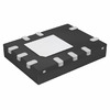
FAN501MPX
Fairchild Semiconductor
IC OFFLINE SWITCH FLYBACK 10MLP
PIC32MX230F064D-I/PT
Microchip Technology
IC MCU 32BIT 64KB FLASH 44TQFP
DS1775R+T&R
Analog Devices Inc./Maxim Integrated
SENSOR DIGITAL -55C-125C SOT23-5
TZM5232B-GS18
Vishay General Semiconductor - Diodes Division
DIODE ZENER 5.6V 500MW SOD80
CL10A475KL8NRNC
Samsung Electro-Mechanics
CAP CER 4.7UF 35V X5R 0603
BFC237321685
Vishay Beyschlag/Draloric/BC Components
CAP FILM 6.8UF 10% 100VDC RADIAL
SE5532AD8R2G
onsemi
IC OPAMP GP 2 CIRCUIT 8SOIC
54LS21DMQB
Texas Instruments
AND GATE, LS SERIES
CS51414ED8
onsemi
IC REG BUCK ADJ 1.5A 8SOIC
5SGXMA5N2F40C2N
Intel
IC FPGA 600 I/O 1517FBGA
DAC8841FS
Analog Devices Inc.
IC DAC 8BIT V-OUT 24SOIC
PVD3354NS
Infineon Technologies
SSR RELAY SPST-NO 240MA 0-300V
EMK212BJ475KG-T
Taiyo Yuden
CAP CER 4.7UF 16V X5R 0805
MC14099BFL1
onsemi
D LATCH, LOW LEVEL TRIGGERED,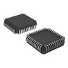
IS82C55AZ96
Renesas Electronics America Inc
IC XPNDR PARALLEL 44PLCC
ADM809-5LARTZ-RL7
Analog Devices Inc.
IC SUPERVISOR MPU 4.63V SOT23 -
GRM2166T1H301JD15D
Murata Electronics
CAP CER 300PF 50V T2H 0805
FAN3850AUC19X
onsemi
IC AMP CLASS AB MONO 6WLCSP
XC2V3000-5BF957C
AMD
IC FPGA 684 I/O 957FCBGA
STMAV335TTR
STMicroelectronics
IC VIDEO SWITCH SP3T 16TSSOP
A451PM
Powerex Inc.
DIODE GP 1.6KV 2500A DO200AC
FQD12P10TM
Fairchild Semiconductor
MOSFET P-CH 100V 9.4A TO252
CL10C150JB8NFNC
Samsung Electro-Mechanics
CAP CER 15PF 50V C0G/NP0 0603
ADT7320UCPZ-R2
Analog Devices Inc.
SENSOR DGTL -40C-150C 16LFCSP
SMAJ30CA
SMC Diode Solutions
TVS DIODE 30VWM 48.4VC SMA
NCP552SQ33T1
onsemi
IC REG LINEAR 3.3V 80MA SC82AB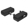
MAX6326UR29+T
Analog Devices Inc./Maxim Integrated
IC SUPERVISOR 1 CHANNEL SOT23-3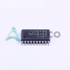
SN74LVC573APWR
Texas Instruments
IC OCTAL TRANSPAR LATCH 20-TSSOP
CPF0603B360RE1
TE Connectivity Passive Product
RES SMD 360 OHM 0.1% 1/16W 0603
AD623AR-REEL
Analog Devices Inc.
IC INST AMP 1 CIRCUIT 8SOIC
LM385BD-2-5
Texas Instruments
IC VREF SHUNT 1.5% 8SOIC
SPX29150T-L-5-0/TR
Diodes Incorporated
IC REG LINEAR 5V 1.5A TO263AB
XC7VX980T-L2FFG1930E
AMD
IC FPGA 900 I/O 1930FCBGA
CC0603ZRY5V9BB153
YAGEO
CAP CER 0.015UF 50V Y5V 0603