
Types of Terminal Block Connectors
This article explains what terminal block connectors are, how they work, and why they are widely used in electrical systems. You’ll learn about their connection methods, different types, mounting techniques, and the advantages and disadvantages they bring. Each section is designed to give you a clear and practical understanding, supported with examples and visuals.
Catalog

Figure 1. Terminal Block Connectors
What is Terminal Block Connectors
Terminal block connectors are modular electrical components designed to join two or more conductors within a protective insulating body. Their primary function is to establish a reliable point of connection between wires while maintaining both safety and organization in electrical assemblies.
Each connector is generally composed of two parts: an insulated housing, typically made of thermoplastic material, and a conductive element, often manufactured from copper or brass alloys. The housing prevents accidental contact and provides mechanical stability, while the conductive element forms the electrical pathway between the wires.
Terminal block connectors are commonly modular, which allows them to be arranged in sequence along standardized mounting systems such as DIN rails. This modularity makes it possible to expand or modify wiring arrangements efficiently without altering the entire setup.
In technical literature, terminal block connectors may also be referred to as terminal strips, screw terminals, barrier strips, connection terminals, feed-through terminals, or pluggable terminal blocks. Although the terminology differs, each designation refers to the same fundamental principle: a structured component that secures and organizes electrical conductors in a consistent and serviceable way.
Connection Methods in Terminal Block Connectors
Terminal block connectors are designed with different mechanisms to hold wires securely in place. The choice of method depends on the application, the type of wire, and how often connections need to be changed. Below are the most common connection methods used in industry.
Screw-in Connection

Figure 2. Screw-in Terminal Block Connector
A screw-in terminal block connector is one of the most commonly used connection methods in electrical systems, employing a screw clamp to secure conductors. In this design, a screw applies mechanical pressure to clamp the wire directly against the conductive element housed inside the connector. This creates a firm and stable electrical pathway.
The strength of the grip ensures that the wire remains securely in place under normal operating conditions. However, excessive tightening can deform or break the conductor, which not only weakens the mechanical hold but may also compromise electrical performance. For this reason, correct torque application is important when installing screw-in connectors.
This method is widely adopted in industrial and commercial wiring because it combines straightforward installation with reliable long-term performance. The design also allows for repeated tightening and loosening when wires need to be replaced or adjusted, making it versatile for a range of applications.
Barrier Connection (Europe Connector)

Figure 3. Barrier Terminal Block Connector
A barrier terminal block connector, often referred to as a Europe connector, incorporates insulating walls between terminals to enhance safety and separation. This type operates in a manner similar to screw-in connectors but incorporates insulating walls between adjacent terminals. These barriers serve an important role in maintaining separation between conductors and reducing the risk of short circuits.
In addition to the insulating partitions, certain models include transparent or removable lids that shield the wiring from dust, moisture, or accidental contact. This added protection makes barrier connectors particularly suitable for environments where conditions may expose the wiring to physical or environmental stress.
By combining the mechanical strength of screw-in clamping with built-in insulation, barrier connectors offer a safer and more controlled method of wire termination. They are widely used in power distribution and control circuits, where reliability and clear separation between connections are required.
Spring-Cage Connection

Figure 4. Spring-Cage Terminal Block Connector
A spring-cage terminal block connector secures wires using spring tension rather than screw pressure, ensuring consistent and maintenance-free contact. In this configuration, the conductor is inserted into the terminal, and the spring element applies constant force to maintain reliable contact with the conductive path.
For proper installation, a ferrule is often crimped onto the wire before insertion. This provides a cleaner connection and prevents the strands of a flexible conductor from spreading. To engage or release the spring, a small screwdriver or a specialized release tool is typically required.
Spring-cage connectors are valued for their speed of installation and consistent performance. Since they do not depend on torque, the quality of the connection is not affected by overtightening, which can occur with screw-based methods. This makes them suitable for applications where repeated connections or quick maintenance is required.
Push-in or Push-Fit Connection

Figure 5. Push-in Terminal Block Connector
A push-in terminal block connector, also known as a push-fit connection, allows direct conductor insertion for quick and reliable wiring. In this design, the conductor is inserted directly into the terminal until it locks securely in place. The mechanism ensures firm electrical contact without the need for additional tightening.
As with spring-cage connectors, many push-in models require the use of ferrules to guarantee consistent and reliable contact. The distinguishing feature of this type is the release button or lever positioned next to the insertion point, which allows the wire to be disengaged quickly. This arrangement simplifies both installation and removal, making the method highly efficient for situations where frequent wiring changes are necessary.
Push-in connectors are widely applied in control panels and modular systems, where quick installation and straightforward maintenance are priorities. Their design supports clean, reliable connections while reducing the time required for wiring tasks.
Insulation Displacement Connection (IDC)

Figure 6. Insulation Displacement Connector (IDC)
An insulation displacement connector (IDC) enables conductors to be inserted without stripping insulation, using metal blades to pierce the insulating layer. Inside the connector, sharp metallic blades pierce through the insulating layer and establish direct contact with the conductor. This process eliminates the need for pre-stripping, which reduces installation time and minimizes handling errors.
IDC connectors were originally developed for solid conductors, where the blades could slice cleanly through the insulation. However, modern designs have been refined to also accommodate stranded wires, broadening their range of applications. This adaptability makes IDC connectors suitable for both telecommunications and industrial wiring, where fast, reliable, and consistent connections are required.
By combining ease of use with dependable performance, IDC connectors provide a practical alternative to traditional methods, particularly in systems where many terminations must be made quickly and consistently.
Pluggable Connection
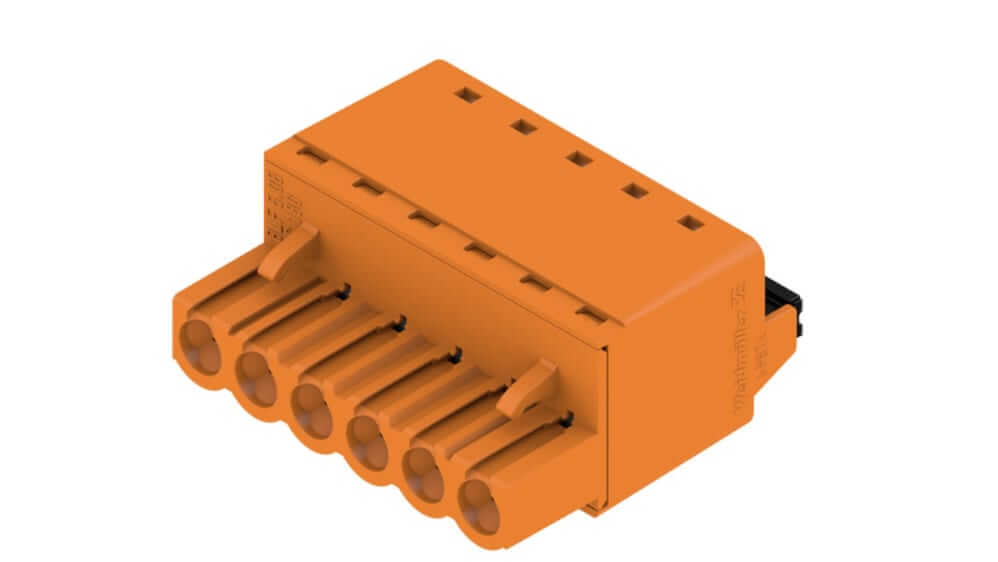
Figure 7. Pluggable Terminal Block Connector
A pluggable terminal block connector operates on a plug-and-socket principle, allowing quick disconnection and reconnection without rewiring. In this arrangement, the wire is secured within a removable plug using a clamping method, and the plug is then inserted into a corresponding socket. This creates a reliable electrical pathway while allowing the connection to be separated quickly when needed.
Pluggable connectors are widely used in equipment that requires frequent disconnection or replacement. Their design eliminates the need for rewiring, which reduces maintenance time and minimizes the risk of damaging conductors during repeated installations. Because of this feature, they are commonly applied in modular systems, control devices, and field wiring setups where flexibility and serviceability are priorities.
This connection method combines ease of use with secure performance, making it well suited for applications that demand both reliability and convenience.
Tab Connection

Figure 8. Tab Connector Terminal Block
A tab-style terminal block connector establishes electrical contact through a flat metal tab, typically paired with crimped or soldered connectors. In this design, the conductor is first prepared with a connector that slides securely onto the tab. The wire may be crimped or soldered to the connector beforehand, ensuring both mechanical stability and electrical continuity.
Some tab connectors are built with hybrid configurations, where one side uses a tab connection and the other side incorporates a screw clamp. This dual arrangement increases flexibility by allowing different termination methods within the same block.
Tab connections are valued for their straightforward assembly and adaptability, making them suitable for applications that require quick attachment and detachment while still providing a dependable connection.
Types of Terminal Block Connectors
Terminal block connectors are not only defined by how they connect wires but also by the specific functions they serve. Depending on the application, different types are designed to handle grounding, protection, or specialized signal requirements.
Ground Terminal Block Connector

Figure 9. Ground Terminal Block Connector
The ground terminal block connector is a specialized component that connects incoming conductors directly to ground via the mounting surface, typically a DIN rail. This connection ensures that any excess electrical charge is safely discharged, which protects both equipment and personnel from potential hazards.
Fuse Terminal Block Connector

Figure 10. Fuse Terminal Block Connector
A fuse terminal block connector integrates wire termination with built-in overcurrent protection, combining connection functionality and circuit safety in a single component. In this configuration, a fuse is placed in series between the input and output, removing the need for external fuse holders and simplifying circuit design.
Many modern fuse terminal blocks incorporate an LED indicator that illuminates when the fuse has blown. This feature provides a quick visual signal of a fault, reducing troubleshooting time and allowing faster replacement.
Thermocouple Terminal Block Connector

Figure 11. Thermocouple Terminal Block Connector
A thermocouple terminal block connector is a specialized design for temperature measurement applications, ensuring accurate signal transmission by preventing unwanted junction voltages. Unlike standard connectors, this design prevents the creation of unwanted junctions that could generate additional voltages and interfere with the accuracy of readings.
In certain models, the internal contact strip is manufactured from the same material as the thermocouple wire itself. This approach ensures consistent thermal and electrical properties across the connection point, which helps maintain precise measurements.
Multi-Level Terminal Block Connectors

Figure 12. Multi-Level Terminal Block Connectors
The image shows examples of multi-level terminal block connectors, designed to save space by stacking multiple wiring levels in a single housing. Each level provides an independent conductive path, so several circuits can be routed vertically instead of spreading across the DIN rail.
Typical designs include double-level and triple-level connectors. A triple-level version has bottom, middle, and top layers, each carrying its own connection. In schematics, these are usually labeled as B, M, and T for clarity during installation and maintenance.
This design makes efficient use of panel depth and width, keeping wiring dense yet orderly. Multi-level connectors mount on standard DIN rails and are available in screw, spring, or push-in styles, often with support for accessories such as marking strips and test points.
Mounting Methods

Figure 13. DIN Rail Mounted Terminal Block Connector
The most common mounting method for terminal block connectors is the DIN rail system, a standardized metal strip used internationally in electrical and control panels. It provides both structural support and precise alignment for connectors and other modular devices.
Terminal blocks are designed to snap or slide onto the rail, which allows quick installation and easy repositioning. For stability, the rail is firmly attached to the backplate of the panel, and stoppers are often added at the ends to prevent connectors from shifting. When different components share the same rail, separators may be used to maintain proper spacing and avoid electrical contact.
In many applications, the DIN rail also acts as a grounding path when correctly bonded to the enclosure. This dual role improves both mechanical stability and electrical safety. Overall, DIN rail mounting ensures that connectors remain secure, accessible, and serviceable throughout the life of the system.
Why Use Terminal Block Connectors
Terminal block connectors provide a practical solution for managing electrical connections in panels and equipment. Instead of relying on soldering or taping conductors, they allow wires to be secured within a stable framework. This results in connections that are not only reliable but also easier to access and maintain.
Flexibility
A key advantage of terminal block connectors is their ability to accommodate changes in wiring. Wires can be added or removed without difficulty, which makes system modifications and upgrades more efficient. This flexibility is particularly useful in settings where adjustments or expansions are part of ongoing maintenance.
Organization
Using terminal block connectors keeps wiring structured and clearly arranged. Neatly aligned connections reduce visual clutter and make circuits easier to trace. This level of organization shortens troubleshooting time and helps ensure that electrical panels remain safe and manageable.
Safety
Terminal block connectors provide secure and stable connections that minimize the risk of loose or faulty wiring. Unlike conductors that are taped or twisted together, these connectors maintain consistent contact, reducing the likelihood of failures that may lead to unsafe conditions.
Durability
Many designs include protective insulation and coverings that extend the service life of the connections. These features reduce wear and shield against accidental contact, which ensures that wiring systems remain dependable even in demanding environments.
Advantages and Disadvantages of Terminal Block Connectors
|
Advantages |
Disadvantages |
|
Low
cost compared to specialized connectors |
Prone
to loosening under vibration or shock |
|
Quick
installation, no soldering required |
Time
consuming for large wire counts |
|
Modular
and scalable, supports clean layouts |
Takes
more space than compact connectors |
|
Safety
features like insulation and test points |
Limited
protection in harsh environments |
|
Easy
maintenance, wires can be replaced or rerouted |
Not
suited for frequent plug/unplug cycles |
|
Material
compatibility helps manage thermal stress |
Over-tightening
can damage conductors |
|
High
wiring density possible with multi-level blocks |
Lower
reliability in some basic designs |
|
Organized
panel layouts and clear routing |
Unsuitable
for ultra-compact or portable devices |
About us
ALLELCO LIMITED
Read more
Quick inquiry
Please send an inquiry, we will respond immediately.
Frequently Asked Questions [FAQ]
1. What is the main purpose of a terminal block connector?
A terminal block connector is used to securely join two or more wires inside a protective housing. It provides both a safe electrical connection and a neat, organized layout for wiring.
2. How do I choose the right connection method for my wiring?
The choice depends on the type of wire, how often you need to change the connection, and the level of reliability you require. For example, screw-in connectors are versatile, while push-in types are faster for frequent adjustments.
3. Can terminal block connectors handle high current?
Yes, many terminal block connectors are designed to carry high currents. However, the capacity varies depending on the size, material, and design of the connector, so you should always check the rated specifications.
4. Why are DIN rails commonly used with terminal blocks?
DIN rails provide a standardized, secure, and adjustable mounting system. They allow multiple connectors to be installed in a compact space while keeping everything aligned and easy to reposition when needed.
5. What is the difference between a fuse terminal block and a regular one?
A fuse terminal block includes an integrated fuse for overcurrent protection, while a regular terminal block only provides the connection. Some fuse blocks also feature LED indicators to show when a fuse has blown, making troubleshooting quicker.

Analog vs. Digital Signals
on July 5th

Fiber-Optic Connectors: SC vs. LC
on September 25th
Popular Posts
-

Complex Instruction Set Computers: How They Changed Computing?
on June 4th 148298
-

USB-C Pinout and Features
on June 4th 129904
-

Using Xilinx Unified Simulation Primitives: A Comprehensive Guide to FPGA Design and Simulation
on June 4th 111778
-

Power Supply Voltages in Electronics: Meaning of VCC, VDD, VEE, VSS, and GND
on June 4th 93324
-

RJ45 Connector Guide: Pinout, Wiring, Cable Types, and Uses
on January 1th 92002
-

The Ultimate Guide to Wire Color Codes in Modern Electrical Systems
The way our electrical systems use colors isn’t just for looks. Each wire color now indicates a specific function, making it easier to identify and handle electrical components correctly during ins...on January 1th 76116
-

Quality (Q) Factor: Equations and Applications
The quality factor, or 'Q', is important when checking how well inductors and resonators work in electronic systems that use radio frequencies (RF). 'Q' measures how well a circuit minimizes energy...on January 1th 74018
-

Purge Valve Guide: Function, Symptoms, Testing, and Replacement for Optimal Engine Performance
The purge valve is a key part of a car’s system that helps keep the air clean by managing fuel vapors before they can escape into the atmosphere. This not only helps the environment by reducing pol...on January 1th 68021
-

Understanding Capacitors and Their Symbols in Circuit Diagrams
Capacitors are small parts used in almost all electronic devices. They store and release electrical energy and are found in things like power supplies, radios, and circuits that help reduce noise. ...on June 4th 57890
-

A23 Battery Specifications and Compatibility
The A23 battery is a small, cylinder-shaped battery with high voltage. Also called 23A, 23AE, or MN21, it runs at 12 volts and much higher than AA or AAA batteries. Its special design make...on January 1th 57471
HOT Part Number
-

TS2937CP50
Taiwan Semiconductor Corporation
0.5A 5V ULTRA LOW DROPOUT VOLTAG
RC0603FR-072R4L
YAGEO
RES 2.4 OHM 1% 1/10W 0603
NOJB686M006RWJ
KYOCERA AVX
CAP NIOB OXID 68UF 20% 6.3V 1210
MC74HC03ANG
onsemi
IC GATE NAND OD 4CH 2-INP 14DIP
6-1761615-5
TE Connectivity AMP Connectors
CONN DIFF ARRAY RCPT 200POS SMD
2EZ15D5
Microsemi Corporation
DIODE ZENER 15V 2W DO204AL
MMSZ5247BT1G
onsemi
DIODE ZENER 17V 500MW SOD123
AN1431M-E1
Panasonic Electronic Components
IC VREF SHUNT ADJ 2% 3HSIP
1N4595
Powerex Inc.
DIODE GP 1.2KV 150A DO205AA
GRM1886S1H750JZ01D
Murata Electronics
CAP CER 75PF 50V S2H 0603
A5358CA
Allegro MicroSystems
IC SMOKE DETECTOR PHOTO 16DIP
GRT31CR61E106ME01L
Murata Electronics
CAP CER 10UF 25V X5R 1206
35YXA470MEFC10X16
Rubycon
CAP ALUM 470UF 20% 35V RADIAL
NC7ST04P5
Fairchild Semiconductor
INVERTER, HST/T SERIES, 1 FUNC,
NJM2246M
Nisshinbo Micro Devices Inc.
IC VIDEO SW 3IN/1OUT 8DMP
M37477E8SP
Renesas Electronics America Inc
8-BIT, OTPROM, 8MHZ
ATMEGA164A-PU
Microchip Technology
IC MCU 8BIT 16KB FLASH 40DIP
3362X-1-501LF
Bourns Inc.
TRIMMER 500 OHM 0.5W PC PIN SIDE -

PE-52626
Pulse Electronics
FIXED IND 220UH 1.5A 420 MOHM TH
NCP15XW152J03RC
Murata Electronics
THERM NTC 1.5KOHM 3950K 0402
FAN501MPX
Fairchild Semiconductor
IC OFFLINE SWITCH FLYBACK 10MLP
PIC32MX230F064D-I/PT
Microchip Technology
IC MCU 32BIT 64KB FLASH 44TQFP
DS1775R+T&R
Analog Devices Inc./Maxim Integrated
SENSOR DIGITAL -55C-125C SOT23-5
TZM5232B-GS18
Vishay General Semiconductor - Diodes Division
DIODE ZENER 5.6V 500MW SOD80
CL10A475KL8NRNC
Samsung Electro-Mechanics
CAP CER 4.7UF 35V X5R 0603
BFC237321685
Vishay Beyschlag/Draloric/BC Components
CAP FILM 6.8UF 10% 100VDC RADIAL
SE5532AD8R2G
onsemi
IC OPAMP GP 2 CIRCUIT 8SOIC
54LS21DMQB
Texas Instruments
AND GATE, LS SERIES
CS51414ED8
onsemi
IC REG BUCK ADJ 1.5A 8SOIC
5SGXMA5N2F40C2N
Intel
IC FPGA 600 I/O 1517FBGA
DAC8841FS
Analog Devices Inc.
IC DAC 8BIT V-OUT 24SOIC
PVD3354NS
Infineon Technologies
SSR RELAY SPST-NO 240MA 0-300V
EMK212BJ475KG-T
Taiyo Yuden
CAP CER 4.7UF 16V X5R 0805
MC14099BFL1
onsemi
D LATCH, LOW LEVEL TRIGGERED,
IS82C55AZ96
Renesas Electronics America Inc
IC XPNDR PARALLEL 44PLCC
ADM809-5LARTZ-RL7
Analog Devices Inc.
IC SUPERVISOR MPU 4.63V SOT23 -
GRM2166T1H301JD15D
Murata Electronics
CAP CER 300PF 50V T2H 0805
FAN3850AUC19X
onsemi
IC AMP CLASS AB MONO 6WLCSP
XC2V3000-5BF957C
AMD
IC FPGA 684 I/O 957FCBGA
STMAV335TTR
STMicroelectronics
IC VIDEO SWITCH SP3T 16TSSOP
A451PM
Powerex Inc.
DIODE GP 1.6KV 2500A DO200AC
FQD12P10TM
Fairchild Semiconductor
MOSFET P-CH 100V 9.4A TO252
CL10C150JB8NFNC
Samsung Electro-Mechanics
CAP CER 15PF 50V C0G/NP0 0603
ADT7320UCPZ-R2
Analog Devices Inc.
SENSOR DGTL -40C-150C 16LFCSP
SMAJ30CA
SMC Diode Solutions
TVS DIODE 30VWM 48.4VC SMA
NCP552SQ33T1
onsemi
IC REG LINEAR 3.3V 80MA SC82AB
MAX6326UR29+T
Analog Devices Inc./Maxim Integrated
IC SUPERVISOR 1 CHANNEL SOT23-3
SN74LVC573APWR
Texas Instruments
IC OCTAL TRANSPAR LATCH 20-TSSOP
CPF0603B360RE1
TE Connectivity Passive Product
RES SMD 360 OHM 0.1% 1/16W 0603
AD623AR-REEL
Analog Devices Inc.
IC INST AMP 1 CIRCUIT 8SOIC
LM385BD-2-5
Texas Instruments
IC VREF SHUNT 1.5% 8SOIC
SPX29150T-L-5-0/TR
Diodes Incorporated
IC REG LINEAR 5V 1.5A TO263AB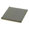
XC7VX980T-L2FFG1930E
AMD
IC FPGA 900 I/O 1930FCBGA
CC0603ZRY5V9BB153
YAGEO
CAP CER 0.015UF 50V Y5V 0603