
Inside RFICs: Components, Design, and Applications in Modern Wireless Electronics
If you’ve ever wondered what powers wireless tech like phones, Wi-Fi, or GPS, this guide has you covered. It walks you through what RFICs are, the parts inside, how they work, and where they’re used. You’ll also get a look at the different types, design tips, how they’re built and tested, and how they stack up against other circuits.Catalog

Figure 1. RFIC Module Mounted on PCB
What is an RFIC?
An RFIC, short for Radio Frequency Integrated Circuit, is a small chip designed to handle radio signals. These are the signals that let your phone connect to Wi-Fi, help your smartwatch sync with your phone, or guide your car’s GPS to your current location. Basically, if a device sends or receives wireless data, there’s a good chance it has an RFIC inside doing the work. What makes RFICs different from regular chips is the kind of signals they’re built to handle. While standard chips work with lower-frequency signals, RFICs are designed for high frequency communication, usually in the megahertz (MHz) to gigahertz (GHz) range. This is the same range used by popular wireless technologies like Bluetooth, Wi-Fi, 5G, and satellite systems. These signals move fast and carry a lot of data, so the circuits that process them need to be accurate, fast, and efficient.
Key Components of RFIC

Figure 2. RFIC structure
• Amplifiers - These helps keep signals strong and clean. As signals travel, they can get weaker or noisy, especially over longer distances. Amplifiers boost them without changing the message.
• Mixers - Mixers shift signals to a frequency that’s easier to handle. They combine the incoming signal with another signal from an oscillator to produce one at a new frequency.
• Oscillators - Oscillators create a stable, repeating signal that sets the pace inside the chip.
• Filters - Filters clean up signals by letting through only the parts you need and blocking the rest.
• Antennas (When integrated)

Figure 3. RFIC with On-Chip Antenna Layout
Some chips now include antennas right on the circuit. These built-in antennas help save space in smaller gadgets.
Working Operation of RFIC
Let's take a look at how everything works together when the chip is in action. Here's a simple step-by-step look at how an RFIC operates.

Figure 4. Typical Signal Path Inside an RF Integrated Circuit (RFIC)
• Step 1. Signal Reception
An external or on-chip antenna receives the incoming RF signal from the environment. The RFIC captures this raw signal and initiates processing.
• Step 2. Amplification
The signal is immediately strengthened by a low-noise amplifier (LNA), improving its detectability while preserving signal clarity. This ensures that weak inputs can still be processed effectively.
• Step 3. Frequency Conversion (Mixing)
The amplified signal is then converted to a more manageable frequency. Using local oscillator input, the RFIC shifts the carrier to an intermediate frequency (IF) or baseband level, preparing it for further manipulation.
• Step 4. Filtering
After frequency translation, the signal is routed through filters to eliminate interference and noise. This step sharpens the desired signal, ensuring accurate downstream processing.
• Step 5. Modulation/Demodulation
In transmit mode, the RFIC superimposes digital data onto a carrier wave. In receive mode, it extracts the original information from the incoming modulated signal using demodulation schemes such as QAM or OFDM.
• Step 6. Power Management
Finally, the RFIC optimizes internal power distribution and thermal behavior to maintain efficient performance. Voltage regulation and biasing circuits help stabilize the entire signal chain.
Applications of RF Integrated Circuits

Figure 5. Smartphone RFIC Components
You already get what RFICs are and how they do their job, so now let’s talk about where they show up in everyday life.
Mobile Phones and Smartphones
RFICs are essential in mobile phones. Inside every smartphone, they manage the radio signals that let you make calls, browse the web, and connect to 4G or 5G networks. These chips control how your phone communicates with nearby cell towers and switch between different frequencies depending on the signal strength or coverage.
Wi-Fi and Wireless Networking Devices
Wi-Fi routers, access points, and wireless cards in laptops and smart home devices all depend on RFICs. These chips manage the radio signals that keep your gadgets connected without the need for cables.
Bluetooth and Short-Range Communication
Whether you're using wireless earbuds, syncing a smartwatch, or tracking fitness goals on a wearable, RFICs keep the signal strong and consistent.
Automotive and Vehicle Systems

Figure 6. Automotive RFIC in Radar System
Cars use RFICs in several areas, from keyless entry and tire pressure monitoring to vehicle-to-vehicle communication. Many newer models include advanced safety features like radar-based systems, where RFICs help generate and process the high-frequency signals needed for things like adaptive cruise control or collision alerts.
GPS and Location Tracking
GPS systems rely on RFICs to catch and strengthen satellite signals, which are often extremely weak by the time they reach Earth. These chips make it possible for your phone, car, or tracking device to determine your exact location.
IoT Devices and Smart Systems
RFICs powering wireless communication in smart home devices like thermostats, doorbells,
cameras, and lights. These devices usually connect through Wi-Fi, Bluetooth, or Zigbee to talk to each other or the cloud.
Industrial and Medical Applications
In industrial settings, RFICs help with wireless monitoring, remote equipment control, and asset tracking. In healthcare, they’re used in things like medical implants, wearable diagnostics, and telemedicine tools. These applications demand stable signals, low power use, and high reliability, which RFICs are specifically designed to deliver.
Types of RF Integrated Circuits
RF CMOS

Figure 7. 2.4 GHz RF CMOS Transceiver with On-Chip Antenna
If you're building or using something like a phone, fitness tracker, or Wi-Fi device, there's a good chance it's running on RF CMOS. It handles common wireless tasks well and doesn’t use much power, which makes it a solid fit for small, battery-powered gadgets.
BiCMOS and SiGe

Figure 8. 8-Element SiGe BiCMOS RFIC Phased-Array Receiver Die Layout
When your setup needs more precision, especially with signal quality, BiCMOS or SiGe chips are worth a look. They give you cleaner performance than regular CMOS and are often used in places like signal towers or communication gear where accuracy matters more than saving space.
MMIC

Figure 9. Q-Band Power Amplifier MMIC Micrograph
MMICs are designed for serious performance. If you’re working with satellites, radar, or other high-frequency systems, this is probably what you're looking at. They can handle more power and tougher signal demands without falling apart under pressure.
RF Power Amplifier ICs

Figure 10. Flexible RF-IC Power Amplifier for Wireless Sensor Applications
When your device needs to send signals farther or punch through interference, these chips do the heavy lifting. They're built to give your signal that extra push so it can stay strong over longer distances.
MEMS, SAW, and BAW

Figure 11. Hybrid SAW Resonator Optical Layout
These chips are all about helping your device filter out noise and stay focused. They’re small but reliable, which makes them great for things like phones or smart devices that work in busy wireless environments.
PLL ICs
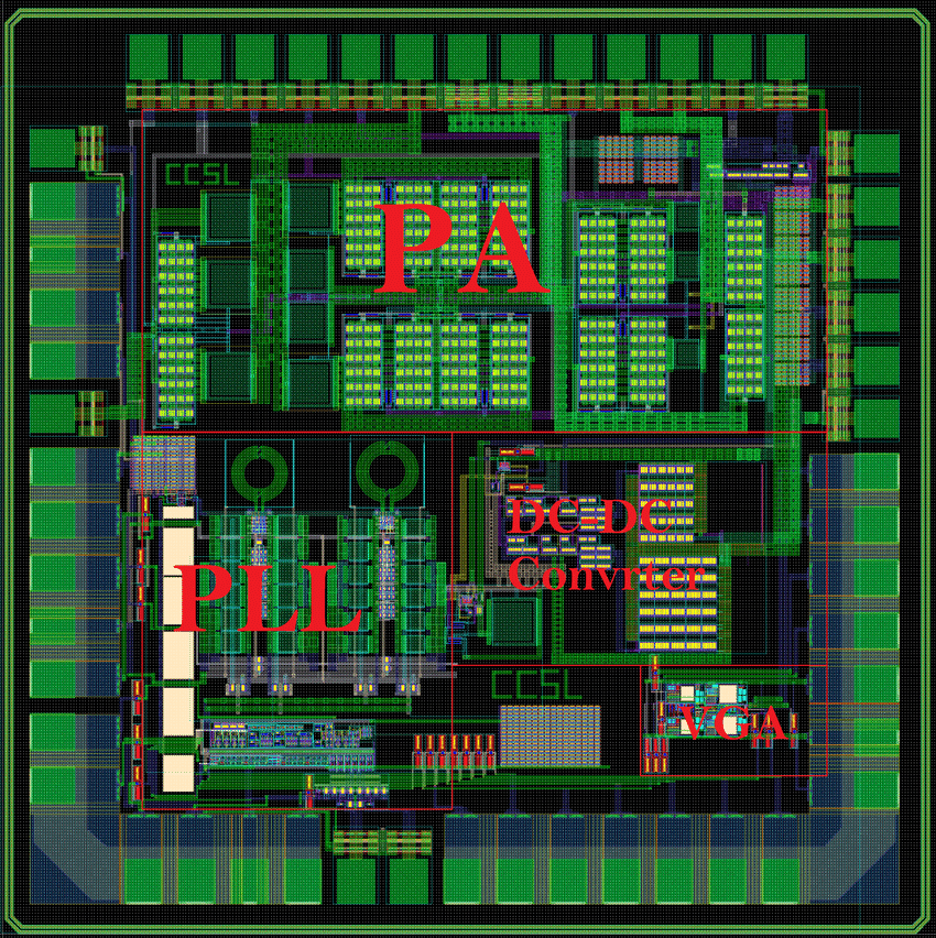
Figure 12. Full-chip layout including PLL, PA, and VGA
PLL chips help keep timing and frequencies in check. They’re useful in anything that needs to stay in sync, like radios, wireless receivers, or systems that jump between frequency bands.
RFIC vs. Other Analog Circuit Designs
RFICs and other analog circuits both deal with continuous signals, but they’re designed for very different jobs. To make things clearer, here’s a side-by-side comparison of how these two designs differ:
|
Feature |
RFIC (Radio Frequency Integrated Circuit) |
Standard Analog Circuit |
|
Frequency
Range |
Typically, megahertz to gigahertz, ideal for Wi-Fi, Bluetooth,
GPS, and 5G |
Usually below a few megahertz, great for audio, sensors, and
power control |
|
Main
Applications |
Smartphones, IoT devices, satellite links, automotive radar |
Audio amplifiers, sensor interfaces, voltage regulators |
|
Key Components |
Mixers,
oscillators, matching networks, low-noise amplifiers |
Operational amplifiers, passive filters, voltage references |
|
Sensitivity to Layout |
Very high.
Even small layout changes can affect performance |
Lower. Layout is more forgiving at lower frequencies |
|
Power
Use Strategy |
Focused on low power at high speeds, perfect for battery-powered
devices |
Designed
for power stability and noise control, not always battery optimized |
|
Typical
Challenges |
Keeping
signal quality high, managing noise, and dealing with heat in small spaces |
Preventing distortion, reducing noise, and maintaining accuracy
without high cost |
RFIC Manufacturing and Testing Process

Figure 13. BiCMOS Fabrication Cross-Section
Designing an RFIC is just the first step. How it's built, what materials are used, and how it's tested all directly affect how it performs. This is especially true for high-frequency applications like 5G, Wi-Fi, or Bluetooth.
What Goes into Making an RFIC
RFICs are typically made using one of three semiconductor technologies: CMOS, BiCMOS, or GaAs.
• CMOS – CMOS is the most widely used. It's affordable, energy-efficient, and works well in digital-based devices like smartphones, wearables, and IoT systems. While it might not offer top performance at ultra-high frequencies, it handles most everyday wireless needs without a problem.
• BiCMOS – BiCMOS combines the low power benefits of CMOS with the fast signal-handling ability of bipolar transistors. It's a good fit for systems that need tighter signal control, such as communication base stations or satellite hardware.
• GaAs – GaAs is more specialized and usually comes at a higher cost, but it delivers excellent performance in high-frequency and high-power situations. You'll often find it in radar systems, advanced satellites, and applications where signal quality takes priority over budget. As chips get smaller and more powerful, the manufacturing process has to be incredibly precise. Even the tiniest flaw in layout or material can mess with performance. That’s why RFICs are built in cleanroom environments using advanced techniques like deep-UV lithography and multi-layer etching. Moving to smaller process nodes means more power in less space, but it also demands tighter control from start to finish.
How RFICs are Tested?

Figure 14. RFIC Testing with Spectrum Analyzer
Once the chip is built, it goes through a careful check to make sure everything works the way it’s supposed to. But testing actually starts earlier. During the planning stage, experts use digital tools to see how the chip might behave. This helps them catch possible problems like signal loss or interference before anything is made.
After the chip is ready, it’s tested in real settings. Special tools measure how strong the signals are, how clear they sound, and how well the chip holds up during use. If the chip is meant to send or receive signals wirelessly, it's also tested inside an actual device to see how well it works when surrounded by other parts.
When everything looks good, and it’s time to make these chips in large numbers, each one is checked again on the production line. This helps spot any chips that might not be working right so that only the good ones make it into your devices.
Conclusion
RFICs help your wireless devices stay connected, run faster, and use less power. You’ll find them in everyday tech like phones, smartwatches, and even cars. These tiny chips are built with care and tested to make sure they work well in real life, not just on paper. As devices keep getting smaller and smarter, RFICs are keeping up by doing more with less.
About us
ALLELCO LIMITED
Read more
Quick inquiry
Please send an inquiry, we will respond immediately.
Frequently Asked Questions [FAQ]
1. What is the difference between RF and RFIC?
RF refers to the entire field of radio frequency electronics, which includes antennas, cables, boards, and circuitry. RFIC is a specific type of chip that handles RF signal processing on a single integrated circuit
2. Why do devices use RFIC instead of separate RF components?
RFICs combine amplifiers, mixers, filters, and oscillators into one compact chip. This saves space, reduces power use, and improves signal quality compared to separate parts. Q3. What frequency range do RFICs work with?
Most RFICs operate in the frequency range of several hundred MHz up to several GHz, which covers cellular, Wi-Fi, Bluetooth, and radar signals
4. What semiconductor materials are used to make RFICs?
RFICs are usually made using CMOS, BiCMOS, and GaAs technologies. CMOS is common for consumer devices, BiCMOS for mixed performance, and GaAs for high-frequency or high power
5. How do RFICs help with power efficiency?
RFICs are designed to use just enough energy to handle signals effectively. Many include power-saving modes or low-power circuits to extend battery life in portable devices.

CR2450 vs CR2032: Can The Battery Be Used Instead?
on December 18th
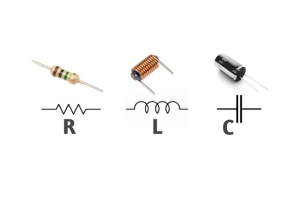
Understanding Resistance, Inductance, and Capacitance in Electrical Circuits
on June 25th
Popular Posts
-

Complex Instruction Set Computers: How They Changed Computing?
on June 4th 148298
-

USB-C Pinout and Features
on June 4th 129904
-

Using Xilinx Unified Simulation Primitives: A Comprehensive Guide to FPGA Design and Simulation
on June 4th 111778
-

Power Supply Voltages in Electronics: Meaning of VCC, VDD, VEE, VSS, and GND
on June 4th 93324
-

RJ45 Connector Guide: Pinout, Wiring, Cable Types, and Uses
on January 1th 92002
-

The Ultimate Guide to Wire Color Codes in Modern Electrical Systems
The way our electrical systems use colors isn’t just for looks. Each wire color now indicates a specific function, making it easier to identify and handle electrical components correctly during ins...on January 1th 76116
-

Quality (Q) Factor: Equations and Applications
The quality factor, or 'Q', is important when checking how well inductors and resonators work in electronic systems that use radio frequencies (RF). 'Q' measures how well a circuit minimizes energy...on January 1th 74018
-

Purge Valve Guide: Function, Symptoms, Testing, and Replacement for Optimal Engine Performance
The purge valve is a key part of a car’s system that helps keep the air clean by managing fuel vapors before they can escape into the atmosphere. This not only helps the environment by reducing pol...on January 1th 68021
-

Understanding Capacitors and Their Symbols in Circuit Diagrams
Capacitors are small parts used in almost all electronic devices. They store and release electrical energy and are found in things like power supplies, radios, and circuits that help reduce noise. ...on June 4th 57890
-

A23 Battery Specifications and Compatibility
The A23 battery is a small, cylinder-shaped battery with high voltage. Also called 23A, 23AE, or MN21, it runs at 12 volts and much higher than AA or AAA batteries. Its special design make...on January 1th 57471
HOT Part Number
-

TS2937CP50
Taiwan Semiconductor Corporation
0.5A 5V ULTRA LOW DROPOUT VOLTAG
RC0603FR-072R4L
YAGEO
RES 2.4 OHM 1% 1/10W 0603
NOJB686M006RWJ
KYOCERA AVX
CAP NIOB OXID 68UF 20% 6.3V 1210
MC74HC03ANG
onsemi
IC GATE NAND OD 4CH 2-INP 14DIP
6-1761615-5
TE Connectivity AMP Connectors
CONN DIFF ARRAY RCPT 200POS SMD
2EZ15D5
Microsemi Corporation
DIODE ZENER 15V 2W DO204AL
MMSZ5247BT1G
onsemi
DIODE ZENER 17V 500MW SOD123
AN1431M-E1
Panasonic Electronic Components
IC VREF SHUNT ADJ 2% 3HSIP
1N4595
Powerex Inc.
DIODE GP 1.2KV 150A DO205AA
GRM1886S1H750JZ01D
Murata Electronics
CAP CER 75PF 50V S2H 0603
A5358CA
Allegro MicroSystems
IC SMOKE DETECTOR PHOTO 16DIP
GRT31CR61E106ME01L
Murata Electronics
CAP CER 10UF 25V X5R 1206
35YXA470MEFC10X16
Rubycon
CAP ALUM 470UF 20% 35V RADIAL
NC7ST04P5
Fairchild Semiconductor
INVERTER, HST/T SERIES, 1 FUNC,
NJM2246M
Nisshinbo Micro Devices Inc.
IC VIDEO SW 3IN/1OUT 8DMP
M37477E8SP
Renesas Electronics America Inc
8-BIT, OTPROM, 8MHZ
ATMEGA164A-PU
Microchip Technology
IC MCU 8BIT 16KB FLASH 40DIP
3362X-1-501LF
Bourns Inc.
TRIMMER 500 OHM 0.5W PC PIN SIDE -

PE-52626
Pulse Electronics
FIXED IND 220UH 1.5A 420 MOHM TH
NCP15XW152J03RC
Murata Electronics
THERM NTC 1.5KOHM 3950K 0402
FAN501MPX
Fairchild Semiconductor
IC OFFLINE SWITCH FLYBACK 10MLP
PIC32MX230F064D-I/PT
Microchip Technology
IC MCU 32BIT 64KB FLASH 44TQFP
DS1775R+T&R
Analog Devices Inc./Maxim Integrated
SENSOR DIGITAL -55C-125C SOT23-5
TZM5232B-GS18
Vishay General Semiconductor - Diodes Division
DIODE ZENER 5.6V 500MW SOD80
CL10A475KL8NRNC
Samsung Electro-Mechanics
CAP CER 4.7UF 35V X5R 0603
BFC237321685
Vishay Beyschlag/Draloric/BC Components
CAP FILM 6.8UF 10% 100VDC RADIAL
SE5532AD8R2G
onsemi
IC OPAMP GP 2 CIRCUIT 8SOIC
54LS21DMQB
Texas Instruments
AND GATE, LS SERIES
CS51414ED8
onsemi
IC REG BUCK ADJ 1.5A 8SOIC
5SGXMA5N2F40C2N
Intel
IC FPGA 600 I/O 1517FBGA
DAC8841FS
Analog Devices Inc.
IC DAC 8BIT V-OUT 24SOIC
PVD3354NS
Infineon Technologies
SSR RELAY SPST-NO 240MA 0-300V
EMK212BJ475KG-T
Taiyo Yuden
CAP CER 4.7UF 16V X5R 0805
MC14099BFL1
onsemi
D LATCH, LOW LEVEL TRIGGERED,
IS82C55AZ96
Renesas Electronics America Inc
IC XPNDR PARALLEL 44PLCC
ADM809-5LARTZ-RL7
Analog Devices Inc.
IC SUPERVISOR MPU 4.63V SOT23 -
GRM2166T1H301JD15D
Murata Electronics
CAP CER 300PF 50V T2H 0805
FAN3850AUC19X
onsemi
IC AMP CLASS AB MONO 6WLCSP
XC2V3000-5BF957C
AMD
IC FPGA 684 I/O 957FCBGA
STMAV335TTR
STMicroelectronics
IC VIDEO SWITCH SP3T 16TSSOP
A451PM
Powerex Inc.
DIODE GP 1.6KV 2500A DO200AC
FQD12P10TM
Fairchild Semiconductor
MOSFET P-CH 100V 9.4A TO252
CL10C150JB8NFNC
Samsung Electro-Mechanics
CAP CER 15PF 50V C0G/NP0 0603
ADT7320UCPZ-R2
Analog Devices Inc.
SENSOR DGTL -40C-150C 16LFCSP
SMAJ30CA
SMC Diode Solutions
TVS DIODE 30VWM 48.4VC SMA
NCP552SQ33T1
onsemi
IC REG LINEAR 3.3V 80MA SC82AB
MAX6326UR29+T
Analog Devices Inc./Maxim Integrated
IC SUPERVISOR 1 CHANNEL SOT23-3
SN74LVC573APWR
Texas Instruments
IC OCTAL TRANSPAR LATCH 20-TSSOP
CPF0603B360RE1
TE Connectivity Passive Product
RES SMD 360 OHM 0.1% 1/16W 0603
AD623AR-REEL
Analog Devices Inc.
IC INST AMP 1 CIRCUIT 8SOIC
LM385BD-2-5
Texas Instruments
IC VREF SHUNT 1.5% 8SOIC
SPX29150T-L-5-0/TR
Diodes Incorporated
IC REG LINEAR 5V 1.5A TO263AB
XC7VX980T-L2FFG1930E
AMD
IC FPGA 900 I/O 1930FCBGA
CC0603ZRY5V9BB153
YAGEO
CAP CER 0.015UF 50V Y5V 0603