View All

Please refer to the English Version as our Official Version.Return

Europe
France(Français) Germany(Deutsch) Italy(Italia) Russian(русский) Poland(polski) Czech(Čeština) Luxembourg(Lëtzebuergesch) Netherlands(Nederland) Iceland(íslenska) Hungarian(Magyarország) Spain(español) Portugal(Português) Turkey(Türk dili) Bulgaria(Български език) Ukraine(Україна) Greece(Ελλάδα) Israel(עִבְרִית) Sweden(Svenska) Finland(Svenska) Finland(Suomi) Romania(românesc) Moldova(românesc) Slovakia(Slovenská) Denmark(Dansk) Slovenia(Slovenija) Slovenia(Hrvatska) Croatia(Hrvatska) Serbia(Hrvatska) Montenegro(Hrvatska) Bosnia and Herzegovina(Hrvatska) Lithuania(lietuvių) Spain(Português) Switzerland(Deutsch) United Kingdom(English)
Asia/Pacific
Japan(日本語) Korea(한국의) Thailand(ภาษาไทย) Malaysia(Melayu) Singapore(Melayu) Vietnam(Tiếng Việt) Philippines(Pilipino)
Africa, India and Middle East
United Arab Emirates(العربية) Iran(فارسی) Tajikistan(فارسی) India(हिंदी) Madagascar(malaɡasʲ)
South America / Oceania
New Zealand(Maori) Brazil(Português) Angola(Português) Mozambique(Português)
North America
United States(English) Canada(English) Haiti(Ayiti) Mexico(español)
HomeProductsIntegrated Circuits (ICs)Embedded - MicrocontrollersATMEGA8535-16PI
ATMEGA8535-16PI Image
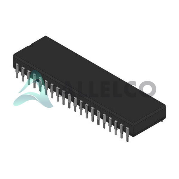
Image may be representation.
See specifications for product details.
EXPRESS OPTION
Payment method

ATMEGA8535-16PI - Atmel

Manufacturer Part Number
ATMEGA8535-16PI
Manufacturer
Atmel
Allelco Part Number
32D-ATMEGA8535-16PI
Warranty
1 Year Allelco Warranty - Find out more
Stock Status:
8,937 pcs available, New & Original
Parts Description
IC MCU 8BIT 8KB FLASH 40DIP
Package
40-PDIP
Data sheet
-
RoHs Status
 
Our certification
In stock: 8937

Required fields are indicated by an asterisk (*)
Please send RFQ, we will respond immediately.

Quantity

Specifications

ATMEGA8535-16PI Tech Specifications
Atmel - ATMEGA8535-16PI technical specifications, attributes, parameters and parts with similar specifications to Atmel - ATMEGA8535-16PI

Product Attribute Attribute Value
Manufacturer Atmel
Voltage - Supply (Vcc/Vdd) 4.5V ~ 5.5V
Supplier Device Package 40-PDIP
Speed 16MHz
Series AVR® ATmega
RAM Size 512 x 8
Program Memory Type FLASH
Program Memory Size 8KB (4K x 16)
Peripherals Brown-out Detect/Reset, POR, PWM, WDT
Package / Case 40-DIP (0.600", 15.24mm)
Package Tube
Product Attribute Attribute Value
Oscillator Type Internal
Operating Temperature -40°C ~ 85°C (TA)
Number of I/O 32
Mounting Type Through Hole
EEPROM Size 512 x 8
Data Converters A/D 8x10b
Core Size 8-Bit
Core Processor AVR
Connectivity I²C, SPI, UART/USART
Base Product Number ATMEGA8535

Environmental & Export Classifications

ATTRIBUTE DESCRIPTION
RoHs Status RoHS non-compliant
ECCN EAR99
HTSUS 8542.31.0001

Frequently Asked Questions(FAQ)

How does the ATMEGA8535-16PI compare to other AVR microcontrollers in terms of program memory size and I/O count, particularly when targeting embedded systems requiring moderate complexity?
The ATMEGA8535-16PI offers 8KB of flash program memory and 32 programmable I/O lines, which positions it between low-end AVRs like the ATtiny series and higher-memory models such as the ATmega16 or ATmega32. This balance makes it suitable for mid-range applications like sensor data acquisition or simple motor control where code footprint stays under 8KB but more peripherals than a tiny are needed. Compared to the ATmega16L, which also has 16MHz operation and similar voltage range, the ATMEGA8535 provides double the program memory at a comparable price point, though with fewer total I/O pins (32 vs. 44). For designs already using 32 I/Os and needing more than 4KB of code space, this device avoids the need to migrate to a larger package.
What are the key limitations of using the ATMEGA8535-16PI in industrial environments, and how do its operating temperature range and power supply requirements impact long-term reliability?
With an operating temperature range of -40°C to +85°C, the ATMEGA8535-16PI meets most industrial standards, but it lacks extended automotive or military-grade qualification. Its voltage tolerance of 4.5V to 5.5V means it cannot be used directly with unregulated 12V automotive buses without a linear regulator, increasing component count and potential failure points. Additionally, the RoHS non-compliance status restricts use in EU-regulated consumer electronics, requiring alternative sourcing strategies. In battery-powered industrial sensors, the 5.5V upper limit caps usable energy from standard alkaline cells, limiting deployment duration unless paired with efficient DC-DC converters.
Can the ATMEGA8535-16PI reliably drive external loads such as LEDs or relays without additional buffering circuitry, and what considerations apply to its GPIO current handling capability?
The ATMEGA8535-16PI’s GPIO pins can source up to 40mA per pin and 200mA total across all ports combined, but continuous operation near these limits risks thermal stress on the microcontroller. Driving multiple high-current loads like relay coils or bright LED arrays typically requires external transistors or drivers. For example, switching a 5V relay drawing 70mA would exceed safe per-pin limits if sourced directly, necessitating a BJT or MOSFET stage. In contrast, small indicator LEDs consuming under 10mA per pin can be driven safely with appropriate series resistors. Designers should derate current usage below 20mA per pin and ensure adequate PCB trace width to handle transient currents during switching.
How does the internal oscillator of the ATMEGA8535-16PI affect timing accuracy in time-critical applications, and what alternatives exist for improved precision?
The ATMEGA8535-16PI uses a calibrated internal RC oscillator running at 16MHz with typical accuracy of ±1% over temperature and voltage variations. While sufficient for UART baud rate generation and basic PWM, this variation may cause unacceptable drift in applications requiring tight clock synchronization, such as multi-sensor fusion or real-time control loops. External crystals offer better stability—a 16MHz ceramic resonator improves accuracy to ±0.5%, while a 16MHz crystal achieves ±20ppm (±0.002%) stability, enabling reliable communication over longer serial links or precise motor speed control. Switching to an external oscillator reduces startup time slightly due to slower crystal boot-up, but improves overall system timing integrity.
When selecting between the PDIP and SOIC packages for the ATMEGA8535-16PI, what practical design trade-offs should engineers consider regarding manufacturability and signal integrity?
The 40-PDIP package of the ATMEGA8535-16PI is ideal for prototyping and through-hole assemblies, offering excellent visibility for debugging and manual soldering. However, its larger footprint increases board area by approximately 30% compared to the equivalent SOIC variant. On PCBs with dense routing layers, the PDIP’s wider lead pitch simplifies layout constraints near adjacent components, reducing crosstalk risk in mixed-signal designs. That said, automated pick-and-place systems favor SOIC for cost efficiency and miniaturization. For high-volume production, converting to SOIC saves space and reduces assembly costs, but requires careful attention to solder joint inspection due to smaller pad sizes. Signal integrity remains unaffected since both packages share identical electrical characteristics.
Is the ATMEGA8535-16PI compatible with modern development tools like Atmel Studio or PlatformIO, and what programming interface options are available for field updates?
Yes, the ATMEGA8535-16PI is fully supported in Atmel Studio (now Microchip Studio) and can be programmed via the built-in high-voltage parallel (HVPP) interface or low-voltage serial protocols. The device supports ISP (In-System Programming) using SPI, allowing reprogramming without removing it from the circuit—critical for firmware updates in deployed systems. However, unlike newer devices, it does not support JTAG or debugWIRE, limiting real-time debugging capabilities compared to ATmega328P-based Arduino boards. Bootloader implementation is possible but limited by only 8KB of flash; adding a bootloader consumes ~512 bytes, leaving minimal space for application code unless compressed or optimized aggressively.
What is the maximum number of ADC channels that can be actively sampled simultaneously on the ATMEGA8535-16PI, and how does this constrain sensor array designs?
The ATMEGA8535-16PI integrates eight 10-bit ADC channels, all multiplexed through a single analog input multiplexer. Only one channel can be sampled at a time unless using external MUX chips or time-division multiplexing in software. This means true simultaneous sampling of multiple sensors isn't feasible without additional hardware. For applications requiring concurrent readings—such as multi-axis accelerometers or gas sensor arrays—engineers must either stagger sampling rates or add discrete analog switches. Alternatively, pairing the ATMEGA8535-16PI with a secondary low-power MCU dedicated to sensing reduces load on the main controller. In practice, most designs sample sequentially at intervals faster than sensor response times to simulate parallelism.
How does the EEPROM size of 512x8 bits in the ATMEGA8535-16PI impact configuration storage in battery-backed systems, and what write endurance considerations apply?
With 512 bytes of EEPROM, the ATMEGA8535-16PI supports modest non-volatile storage needs such as calibration offsets, user preferences, or log buffers. Each byte endures approximately 100,000 write cycles, making it unsuitable for frequent logging scenarios without wear-leveling algorithms. In contrast, modern FRAM-based MCUs offer unlimited writes but come at higher cost. For typical battery-backed configurations storing parameters once at boot or infrequently during operation, 512 bytes suffices. Engineers should avoid dynamic allocation within EEPROM and instead predefine fixed structures to prevent fragmentation and accidental overwrites. Data retention is rated at 20 years at 85°C, aligning with industrial longevity expectations.
What brownout detection and watchdog timer features are included in the ATMEGA8535-16PI, and how can they enhance system robustness in noisy power environments?
The ATMEGA8535-16PI includes an adjustable brown-out detection (BOD) circuit that resets the MCU when Vcc drops below a threshold selectable via fuse bits (typically 2.7V, 4.3V, or off). This prevents erratic behavior during power-up transients or brownouts. Combined with a programmable watchdog timer (WDT) capable of intervals from 16ms to 8s, the device can recover from software hangs caused by EMI-induced lockups. For example, in a motor control application powered by a switching supply prone to ripple, enabling BOD at 4.3V and WDT at 2s ensures clean restarts without manual reset intervention. Unlike software-only monitoring, this hardware-based protection operates even during stack overflows or interrupt storms.
How does the UART/USART module in the ATMEGA8535-16PI handle baud rate errors in asynchronous communication, and what clock source choices minimize framing issues?
Baud rate accuracy depends critically on the chosen clock source. Using the internal 16MHz RC oscillator introduces up to ±1% frequency error, which translates to ±2% baud rate deviation—acceptable for standard 9600 or 19200 bps but problematic at higher speeds like 115200 bps, where even 2% error causes frequent framing errors. Switching to a stable external crystal reduces this to ±0.002%, ensuring reliable communication with host systems. Additionally, the UART supports auto-baud detection and fractional baud rate generators, allowing fine-tuning even with minor clock inaccuracies. In multi-drop RS-485 networks, consistent timing across nodes is essential; thus, all slaves sharing the same master should use identical clock sources or synchronized oscillators.
Can the ATMEGA8535-16PI implement pulse-width modulation (PWM) with sub-microsecond resolution, and what hardware resources limit advanced timing control?
The ATMEGA8535-16PI provides six PWM channels: three 8-bit (Timer/Counter2) and three 16-bit (Timer/Counter0 and Timer/Counter1). At 16MHz clock, the 8-bit timers yield a minimum PWM period of 16μs (62.5kHz), limiting resolution for low-frequency applications. The 16-bit timers extend this to 4096 steps, offering finer duty control down to 0.024% resolution at 16MHz. However, analog comparators and dead-time insertion (in fast PWM mode) consume peripheral resources that might conflict with ADC sampling or communication tasks. For precise LED dimming or servo control, 16-bit timers suffice; for ultrasonic transducer driving above 50kHz, external gate drivers are preferable due to output slew rate limitations of the MCU pins.
What are the implications of the ATMEGA8535-16PI’s lack of integrated CAN or Ethernet support, and how do engineers typically address connectivity in industrial automation applications?
As a legacy 8-bit AVR, the ATMEGA8535-16PI lacks native support for industrial protocols like CAN, USB, or Ethernet. To interface with modern fieldbus networks, engineers commonly pair it with external transceivers such as MCP2515 for CAN or ENC28J60 for Ethernet. For example, a building automation node using Modbus RTU over RS-485 would require a MAX485 transceiver plus level shifting, increasing bill-of-materials cost by $1–2 per unit. While this adds complexity, it preserves the ATMEGA8535-16PI’s strengths in deterministic timing and low interrupt latency. Alternatives include migrating to ARM Cortex-M0+ MCUs with built-in peripherals, though this sacrifices code density and real-time performance for simpler protocol stacks.

Parts with Similar Specifications

The three parts on the right have similar specifications to Atmel ATMEGA8535-16PI

Product Attribute ATMEGA8535-16PI ATMEGA8535-16PC ATMEGA8535-16PU ATMEGA8535-16PJ
Part Number ATMEGA8535-16PI ATMEGA8535-16PC ATMEGA8535-16PU ATMEGA8535-16PJ
Manufacturer Microchip Technology Microchip Technology Microchip Technology Microchip Technology
Package - Tape & Reel (TR) Tube Tape & Reel (TR)
RAM Size - - - -
Series - - - -
Supplier Device Package - 196-NFBGA (12x12) 16-PDIP 64-VQFN (9x9)
Operating Temperature - -40°C ~ 85°C 0°C ~ 70°C -40°C ~ 85°C
Peripherals - - - -
Speed - - - -
Package / Case - 196-LFBGA 16-DIP (0.300', 7.62mm) 64-VFQFN Exposed Pad
Connectivity - - - -
Number of I/O - - - -
Program Memory Size - - - -
Core Processor - - - -
Voltage - Supply (Vcc/Vdd) - - - -
Mounting Type - Surface Mount Through Hole Surface Mount
EEPROM Size - - - -
Data Converters - - - -
Base Product Number - DAC34H84 MAX500 ADS62P42
Oscillator Type - - - -
Program Memory Type - - - -
Core Size - - - -

Customer Reviews

Evaluation: 10 Articles

  • Dani***alkerTech
    Jun 1, 2026

    Product works, but setup took more effort than expected. Once configured the MCU ran reliably, although documentation support felt older compared with newer platforms. Fine for maintenance projects.

  • Yuki***aka88
    May 26, 2026

    信号通信プロジェクトでこのRS-485トランシーバーを使用しました。設置は簡単で、長距離ケーブルでも通信は安定していました。消費電力も、以前使用していたものより低くなっています。

  • Stev***aker
    May 20, 2026

    Solid diode for power rectification. Works well in switching circuits.

  • Bran***Lewis
    May 11, 2026

    Compact FPGA with good performance. Suitable for basic signal processing tasks.

  • Oliv***arris
    May 7, 2026

    Reliable I/O expander. Works well in embedded control applications.

  • Jess***Jones
    Apr 17, 2026

    It offers good value for the price, and the specifications match the description. I’ve been using it for two days with no issues, and I’ll definitely buy it again if I need it in the future.

  • Mich***Smith
    Apr 17, 2026

    Shipping was on time, the component pins are neatly aligned, and I tested 10 of them with a multimeter—all readings were within the specified range. Highly recommended.

  • Aman***arris
    Apr 3, 2026

    It was great—the entire process, from placing the order to receiving the package, went very smoothly. The components were consistent, the price was fair, and I had a very pleasant shopping experience.

  • Mike***nch
    Apr 3, 2026

    Better than expected! The resistance and capacitance readings were spot-on, and it passed the test on the first try. The service was reliable, and the packaging was thoughtful—I highly recommend it.

  • Daic***K.
    Mar 23, 2026

    Very good. No issue after long time testing.

Write a Review

Your Email address will not be published.

Shipment

Delivery Time

In-stock items can be shipped within 24 hours. Some parts will be arranged for delivery within 1-2 days from the date all items arrive at our warehouse. And Allelco ships order once a day at about 17:00, except Sunday. Once the goods are shipped, the estimated delivery time depends on the shipping methods and Delivery destination. The table below shows are the logistic time for some common countries.

Delivery Cost

  1. Use your express account for shipment if you have one.
  2. Use our account for the shipment. Refer to the table below for the approximate charges.
(Different time frame / countries / package size has different price.)

Delivery Method

  1. Global Common Shipment by DHL / UPS / FedEx / TNT / EMS / SF we support.
  2. Others more shipping ways, please get in touch with your customer manager.

Common Countries Logistic Time Reference
Region Country Logistic Time(Day)
America United States 5
Brazil 7
Europe Germany 5
United Kingdom 4
Italy 5
Oceania Australia 6
New Zealand 5
Asia India 4
Japan 4
Middle East Israel 6
DHL & FedEx Shipment Charges Reference
Shipment charges(KG) Reference DHL(USD$)
0.00kg-1.00kg USD$30.00 - USD$60.00
1.00kg-2.00kg USD$40.00 - USD$80.00
2.00kg-3.00kg USD$50.00 - USD$100.00
Note:
The above table is for reference only. There may have some data bias for the uncontrollable factors.
Contact us if you have any questions.
  • QC (Quality Warranty)
  • Payment Support
  • Packaging
  • Certifications & Memberships

QC (Quality Warranty)

Allelco is committed to exceeding customer expectations through customer service excellence, order accuracy, and on-time delivery.
This is achieved through our commitment to the continual improvement of our processes, services, and products.


Strict quality inspection builds a solid foundation for electronic component quality.
  1. Visual inspection
  2. Performance testing and reliability verification
  3. Standardized full-process testing
  4. Precise control of every parameter
We eliminate defective components and ensure the stable operation of electronic devices through professional quality standards.

Payment Support

The payment method can be chosen from the methods shown below: Wire Transfer (T/T, Bank Transfer), Western Union, Credit card, PayPal.
  • HKBea
  • Paypal
  • MasterCard
  • Western-Union
  • VISA
Stable Delivery, Sincere Partnership — Your Faithful Supply Chain Partner
  • Efficient Supply Management
  • Cost-Saving Procurement
  • Fast Sourcing & Delivery
Contact us if you have any questions.

Packaging

Electrostatic Discharge Protection and Handling

All electrostatic-sensitive components are handled in accordance with electrostatic discharge control procedures. The products are hermetically sealed in anti-static safe packaging to prevent electrostatic damage. Appropriate labeling is also applied for identification and traceability. This ensures product integrity during storage, handling and transportation.


ESD

Certifications & Memberships

Third-party certified, strict quality control. Our certification
  • ISO 9001: 2015
  • ISO 13485: 2016
  • ISO 14001: 2015
  • ISO 28000: 2007
  • ISO 45001: 2018
  • GB/T 27922-2011
  • SMTA
  • IPC
  • ESD
  • PSMA
ATMEGA8535-16PI Image

ATMEGA8535-16PI

Atmel
32D-ATMEGA8535-16PI

Want a better price? Add to Cart and Submit RFQ now, we'll contact you immediately.

0 RFQ
Shopping cart (0 Items)
It is empty.
Compare List (0 Items)
It is empty.
Feedback

Your feedback matters! At Allelco, we value the user experience and strive to improve it constantly.
Please share your comments with us via our feedback form, and we'll respond promptly.
Thank you for choosing Allelco.

Subject
E-mail
Comments
Captcha
Drag or click to upload file
Upload File
types: .xls, .xlsx, .doc, .docx, .jpg, .png and .pdf.
Max file size: 10MB