

ATMEGA8535-16PU (1)
Manufacturer Part Number
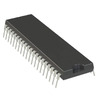
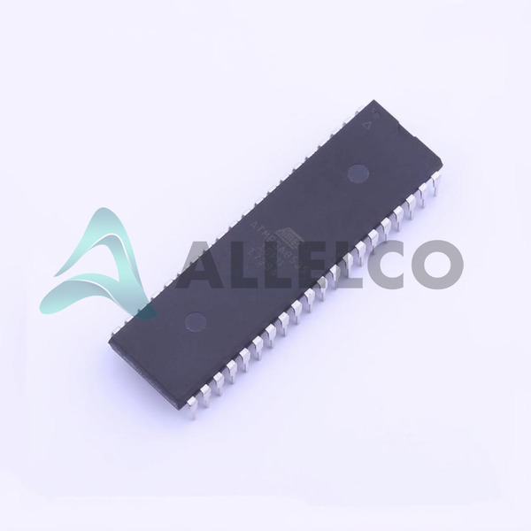
ATMEGA8535-16PU
Manufacturer
Microchip Technology
Introduction
The ATMEGA8535-16PU is part of Microchip's popular AVR ATmega series of 8-bit microcontrollers, designed for a broad range of applications and known for its reliability and performance.
Product Features and Performance
8-Bit AVR Core Processor
16MHz Clock Speed
32 Programmable I/O Lines
8KB Flash Memory
512 Bytes EEPROM
512 Bytes Internal SRAM
In-system Programmable via SPI Port
Internal Oscillator for Simplified Operation
Product Advantages
High Performance with Low Power Consumption
Advanced RISC Architecture with 32 x 8 General Purpose Working Registers
Fully Static Operation for Power Saving
Up to 16 MIPS Throughput at 16 MHz
ATMEGA8535-16PU (2)
Key Technical Parameters
I2C, SPI, UART/USART Connectivity
Brown-out Detect/Reset, POR, PWM, WDT Peripherals
A/D Converter with 8 Channels and 10-bit Resolution
Operating Voltage Range of 4.5V to 5.5V
Through Hole Mounting with 40-PDIP Packaging
Quality and Safety Features
Extended Temperature Range from -40°C to 85°C
Data Retention Rated for 20 years at 85°C
Compatibility
Compatible with Microchip's Range of Development Tools and Software
Application Areas
Industrial Control Systems
Automotive
Consumer Electronics
Internet of Things (IoT) Devices
Robotics and Automation
Product Lifecycle
Active Status with Continued Manufacturer Support
Not Nearing Discontinuation
Several Key Reasons to Choose This Product
Robust Instruction Set Facilitates Programming and Reduces Time to Market
On-chip Debug Capability Improves Productivity
Wide Ecosystem of Development Tools and Community Support
Suitable for both Rapid Prototyping and Volume Production
Scalable Line of Microcontrollers for Future Upgrades

 ATMEGA8535-16MUAtmelIC MCU 8BIT 8KB FLASH 44VQFN
 ATMEGA8535L-8AIAtmelIC MCU 8BIT 8KB FLASH 44TQFP
 ATMEGA8535L-8ACMicrochip TechnologyIC MCU 8BIT 8KB FLASH 44TQFP
 ATMEGA8535L-8AAtmel
 ATMEGA8535L-8JCMicrochip TechnologyIC MCU 8BIT 8KB FLASH 44PLCC


