
AM26LV31IDR (1)
Manufacturer Part Number
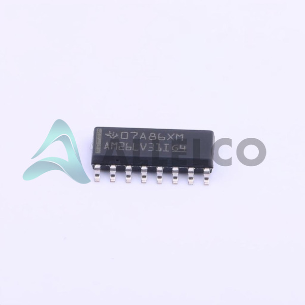
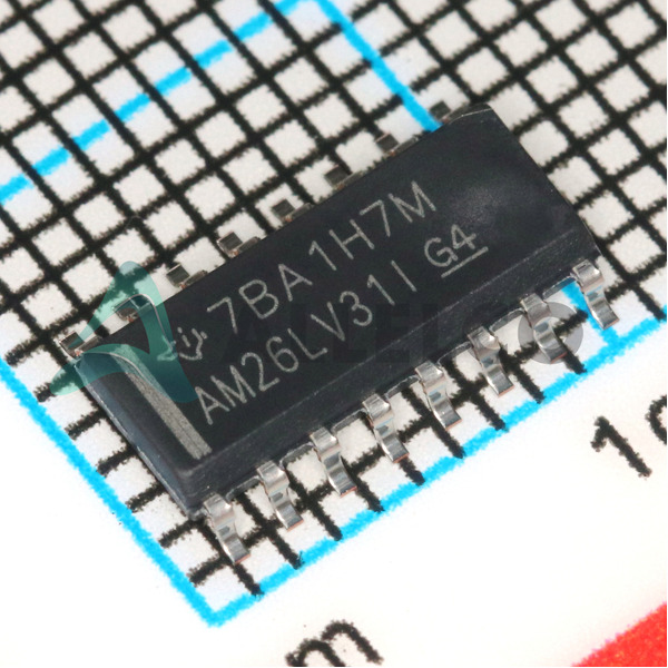
AM26LV31IDR
Manufacturer
Texas Instruments
Introduction
The AM26LV31IDR is an RS422, RS485 driver from Texas Instruments designed for high-speed data transmission over differential communication lines.
AM26LV31IDR (2)
Product Features and Performance
Designed for RS422, RS485 protocols
Operates with a supply voltage of 3V to 3.6V
Supports a wide operating temperature range of -40°C to 85°C
Features four drivers
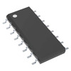
Packaged in a 16-SOIC format
Product Advantages
Efficient for systems requiring high-speed data communication
Robust temperature range ensuring reliability in varied environments
Compact 16-SOIC package ideal for space-constrained applications
Key Technical Parameters
Type: Driver
Voltage Supply: 3V ~ 3.6V
Operating Temperature: -40°C ~ 85°C
Number of Drivers: 4
Package / Case: 16-SOIC
Quality and Safety Features
Compliant with the standard RS422, RS485 protocols ensuring safe and reliable communication
AM26LV31IDR (3)
Compatibility
Specifically compatible with systems implementing RS422 or RS485 communication protocols
Application Areas
Industrial automation
Telecommunications
Data acquisition systems
Product Lifecycle
Current Status: Active
Not nearing discontinuation and replacements or upgrades are currently not required
Several Key Reasons to Choose This Product
High reliability in diverse environmental conditions thanks to a wide operating temperature range
Space-efficient packaging suitable for compact systems
Easy integration into existing systems with standard compliance
Enhanced durability for industrial and telecommunications applications


 AM26LV31IDTexas Instruments
 AM26LV32CDTexas Instruments
 AM26LV31INSRTexas InstrumentsIC DRIVER 4/0 16SO
 AM26LV31ESDREPTexas InstrumentsIC DRIVER 4/0 16SOIC
 AM26LV32CDRTexas InstrumentsIC RECEIVER 0/4 16SOIC
 AM26LV31INSTexas InstrumentsLINE DRIVER, 4 FUNC, 4 DRIVER
 AM26LV31EINSRTexas InstrumentsIC DRIVER 4/0 16SO


