

BQ25606RGER (1)
Manufacturer Part Number
BQ25606RGER
Manufacturer
Texas Instruments
Introduction
Integrated Circuit (IC) for battery charging
Product Features and Performance
Programmable constant current/constant voltage Li-Ion/Li-Polymer battery charger
Supports 1-cell Li-Ion/Li-Polymer batteries
Charges at up to 3A
Integrated boost converter with up to 13.5V output voltage
Supports USB interface
Product Advantages
Programmable charge current and termination current
Fault protection: over-temperature, over-voltage, short-circuit
High efficiency power conversion

BQ25606RGER (2)
Key Technical Parameters
Operating temperature range: -40°C to 85°C
Input voltage: Up to 13.5V
Battery voltage: 4.4V
Supports 1-cell Li-Ion/Li-Polymer batteries
Quality and Safety Features
RoHS3 compliant
24-VQFN (4x4) package with exposed pad for enhanced thermal performance
Compatibility
Surface mount package for easy board integration
Application Areas
Portable electronics
Power banks
Wearable devices
Product Lifecycle
This product is currently in production and available for purchase.
Key Reasons to Choose This Product
Programmable and flexible charging solution
Robust fault protection for safe operation
High efficiency power conversion for extended battery life
Small package size for compact designs


 BQ25611DEVMTexas InstrumentsEVAL BOARD FOR BQ25611D
 BQ25616EVMTexas InstrumentsBQ25616EVM
 BQ25611DRTWTTexas InstrumentsIC BATT CHG LI-ION 1CELL 24WQFN
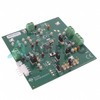
 BQ25606EVM-772Texas InstrumentsEVAL BOARD FOR BQ25606
 BQ25601RTWTTexas InstrumentsIC BATT CHG LI-ION 1CELL 24WQFN
 BQ25611DRTWRTexas InstrumentsIC BATT CHG LI-ION 1CELL 24WQFN
 BQ25601EVM-877Texas InstrumentsEVAIL MOD
 BQ25616JEVMTexas InstrumentsBQ25616JEVM
 BQ25601DEVM-877Texas InstrumentsDEVELOPMENT POWER MANAGEMENT
 BQ25606


