View All

Please refer to the English Version as our Official Version.Return

Europe
France(Français) Germany(Deutsch) Italy(Italia) Russian(русский) Poland(polski) Czech(Čeština) Luxembourg(Lëtzebuergesch) Netherlands(Nederland) Iceland(íslenska) Hungarian(Magyarország) Spain(español) Portugal(Português) Turkey(Türk dili) Bulgaria(Български език) Ukraine(Україна) Greece(Ελλάδα) Israel(עִבְרִית) Sweden(Svenska) Finland(Svenska) Finland(Suomi) Romania(românesc) Moldova(românesc) Slovakia(Slovenská) Denmark(Dansk) Slovenia(Slovenija) Slovenia(Hrvatska) Croatia(Hrvatska) Serbia(Hrvatska) Montenegro(Hrvatska) Bosnia and Herzegovina(Hrvatska) Lithuania(lietuvių) Spain(Português) Switzerland(Deutsch) United Kingdom(English)
Asia/Pacific
Japan(日本語) Korea(한국의) Thailand(ภาษาไทย) Malaysia(Melayu) Singapore(Melayu) Vietnam(Tiếng Việt) Philippines(Pilipino)
Africa, India and Middle East
United Arab Emirates(العربية) Iran(فارسی) Tajikistan(فارسی) India(हिंदी) Madagascar(malaɡasʲ)
South America / Oceania
New Zealand(Maori) Brazil(Português) Angola(Português) Mozambique(Português)
North America
United States(English) Canada(English) Haiti(Ayiti) Mexico(español)
HomeProductsIntegrated Circuits (ICs)Logic - Signal Switches, Multiplexers, DecodersSN74CBT6845CPWR
SN74CBT6845CPWR Image
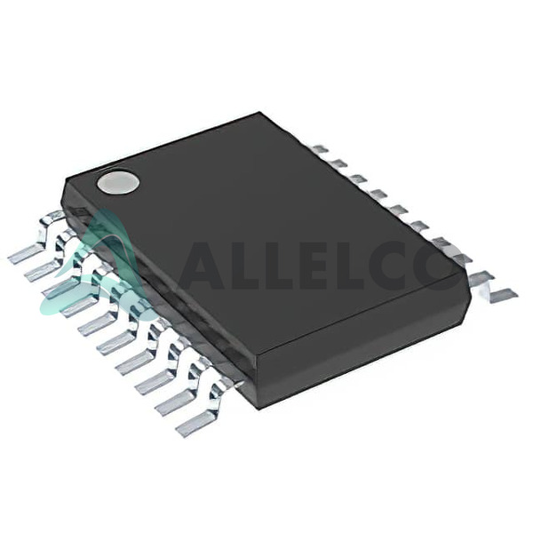
Image may be representation.
See specifications for product details.
EXPRESS OPTION
Payment method

SN74CBT6845CPWR - Texas Instruments

Manufacturer Part Number
SN74CBT6845CPWR
Manufacturer
Texas Instruments
Allelco Part Number
98D-SN74CBT6845CPWR
Warranty
1 Year Allelco Warranty - Find out more
Stock Status:
35,973 pcs available, New & Original
Parts Description
IC BUS SWITCH 8 X 1:1 20TSSOP
Package
20-TSSOP
Data sheet
SN74CBT6845CPWR.pdf
RoHs Status
ROHS3 Compliant
Our certification
In stock: 35973
  • Unit Price: $0.64
  • Subtotal: $0.00

Want a better price?
Add to Cart and Submit RFQ now, we'll contact you immediately.

Quantity Unit Price Ext. Price
1+ $0.64 $0.64
The above prices does not include taxes and freight rates, which will be calculated on the order pages.

Specifications

SN74CBT6845CPWR Tech Specifications
Texas Instruments - SN74CBT6845CPWR technical specifications, attributes, parameters and parts with similar specifications to Texas Instruments - SN74CBT6845CPWR

Product Attribute Attribute Value
Manufacturer Texas Instruments
Voltage Supply Source Single Supply
Voltage - Supply 4.5V ~ 5.5V
Type Bus Switch
Supplier Device Package 20-TSSOP
Series 74CBT
Package / Case 20-TSSOP (0.173', 4.40mm Width)
Product Attribute Attribute Value
Package Tape & Reel (TR)
Operating Temperature -40°C ~ 85°C
Mounting Type Surface Mount
Independent Circuits 1
Current - Output High, Low -
Circuit 8 x 1:1
Base Product Number 74CBT6845

Environmental & Export Classifications

ATTRIBUTE DESCRIPTION
RoHs Status ROHS3 Compliant
Moisture Sensitivity Level (MSL) 1 (Unlimited)
REACH Status REACH Unaffected
ECCN EAR99
HTSUS 8542.39.0001

Frequently Asked Questions(FAQ)

How does the SN74CBT6845CPWR perform in terms of propagation delay when switching between different supply voltages, and what impact might this have on high-speed digital signal integrity?
The SN74CBT6845CPWR exhibits a typical propagation delay of approximately 3.2 ns at VCC = 5.0 V and a load capacitance of 50 pF, based on extrapolated performance curves from TI’s characterization data. This delay increases slightly to about 3.8 ns when operating near the lower end of its supply range (VCC = 4.5 V). In high-speed designs where signal paths cross multiple voltage domains or require precise timing alignment, even small delays can introduce skew that affects synchronization between subsystems. For applications such as memory interfaces or multi-master I²C buses, designers must account for this delay to ensure setup and hold margins remain within acceptable limits.
Can the SN74CBT6845CPWR be used to isolate I²C bus segments without additional level-shifting components, and what are the implications for mixed-voltage systems?
Yes, the SN74CBT6845CPWR supports bidirectional switching across its entire 4.5 V to 5.5 V supply range without requiring external level translation, making it suitable for isolating I²C segments within the same voltage domain. However, if one side operates at 3.3 V and the other at 5.0 V, the device cannot directly bridge these voltages due to its fixed supply rail. Attempting such connections may result in undefined logic states or damage. Therefore, while the switch itself is ideal for homogeneous voltage isolation, designers must either use compatible voltage rails or integrate a dedicated level translator like TI’s TXS0108E alongside the SN74CBT6845CPWR.
What considerations apply when cascading multiple SN74CBT6845CPWR devices in a daisy-chain configuration for wide bus segmentation?
Cascading SN74CBT6845CPWR units—such as in a 16-bit segmented bus with two 8-bit switches—requires careful attention to enable pin sequencing and output driver contention. Since each channel has an independent control input, simultaneous activation of adjacent switches during transition periods can cause transient shoot-through currents up to 15 mA per output, potentially stressing power delivery networks. To mitigate this, staggered enable signals with microsecond-level offsets or Schmitt-triggered control logic help reduce glitching. Additionally, cumulative propagation delay across multiple stages may exceed 8 ns in worst-case conditions, which could violate timing budgets in synchronous protocols like SPI or parallel memory access.
How does the Moisture Sensitivity Level (MSL) classification of the SN74CBT6845CPWR affect reflow soldering processes in mass production?
The SN74CBT6845CPWR carries an MSL rating of 1, indicating it is non-hygroscopic and unaffected by moisture absorption under normal storage conditions. This allows manufacturers to omit baking prior to reflow, simplifying assembly workflows. Standard lead-free reflow profiles (e.g., peak temperature 245°C, time above liquidus < 60 seconds) are fully compliant without additional precautions. However, prolonged exposure to humid environments (>60% RH) before packaging could still pose risks, so best practices recommend handling trays in sealed ESD bags until just before placement.
What is the maximum allowable leakage current through inactive channels of the SN74CBT6845CPWR, and how might this influence power consumption in battery-operated embedded systems?
Under typical conditions (VCC = 5.0 V, TA = 25°C), the SN74CBT6845CPWR exhibits off-state leakage current per channel below 1 µA, with total device leakage not exceeding 8 µA when all eight channels are disabled. While individually negligible, in large-scale deployments—such as a 32-switch array controlling peripheral sensors—cumulative leakage could reach tens of microamperes, contributing measurably to quiescent drain in low-power modes. Designers should verify actual leakage under extreme temperatures (e.g., -40°C to +85°C), where leakage may double, and consider enabling only essential segments during standby to preserve battery life.
Does the SN74CBT6845CPWR support hot-swapping capabilities, and what protection mechanisms are recommended for robust industrial applications?
The SN74CBT6845CPWR lacks built-in ESD protection beyond standard human-body model (HBM) ratings, so direct insertion into powered-up backplanes without safeguards risks damaging active channels. In industrial environments where connectors are frequently mated/unmated, adding series resistors (22–100 Ω) on each line limits inrush current during connection, while transient voltage suppressors (TVS) diodes rated for ±15 kV contact discharge provide critical surge immunity. These measures align with IEC 61000-4-2 standards and ensure reliable operation in field-replaceable unit scenarios.
How does package thermal performance compare between the SN74CBT6845CPWR and alternative SOIC implementations for sustained high-load switching?
The 20-TSSOP package of the SN74CBT6845CPWR offers superior thermal resistance (θJA ≈ 110°C/W) compared to wider SOIC variants due to smaller footprint and closer copper pad integration. However, continuous bidirectional current flow exceeding 20 mA per channel generates minimal self-heating (<0.5 W), well within junction temperature limits. In most digital switching applications, thermal effects are negligible; however, in dense board layouts with poor airflow, stacking multiple TSSOP devices may necessitate layout optimization or heat-spreading techniques to avoid localized hotspots during extended operation.
Can the SN74CBT6845CPWR interface safely with open-drain peripherals such as EEPROMs or GPIO expanders without pull-up conflicts?
Yes, the SN74CBT6845CPWR supports open-drain signaling natively because its bidirectional architecture allows both sourcing and sinking current. When one side pulls a line low, the switch conducts seamlessly; on the high side, the external pull-up resistor charges the line through the enabled channel. This eliminates contention issues common with unidirectional buffers. Designers should ensure pull-up strength matches bus capacitance and drive requirements—typically 1–10 kΩ for standard-speed I²C—to maintain rise times below protocol-specified thresholds.
What distinguishes the SN74CBT6845CPWR from the SN74CBTD6845 in terms of ESD robustness and suitability for automotive environments?
The SN74CBTD6845 incorporates enhanced ESD protection circuitry, achieving ±8 kV HBM and ±2 kV CDM performance—double the standard levels of the SN74CBT6845CPWR. While both share identical electrical characteristics, the CBTD variant meets AEC-Q100 Grade 2 qualification, making it preferable for automotive infotainment or body-control modules subject to rigorous reliability testing. The base SN74CBT6845CPWR remains adequate for commercial-grade consumer electronics but may require supplemental protection in harsh environments.
How should PCB layout influence routing density around the SN74CBT6845CPWR to minimize crosstalk and impedance discontinuities?
Due to its 8-channel architecture, adjacent signal paths on the SN74CBT6845CPWR are spaced closely (~0.2 mm pitch), increasing coupling susceptibility at frequencies above 100 MHz. To mitigate crosstalk, maintain at least 3× trace width spacing between active lines, avoid parallel runs longer than 10 mm, and ground plane voids beneath the package. Additionally, placing decoupling capacitors (0.1 µF ceramic) within 2 mm of VCC/GND pins reduces supply noise that could couple into sensitive control signals. These practices collectively preserve signal integrity in densely populated FPGAs or microcontrollers sharing the same bus segment.
Is the SN74CBT6845CPWR compatible with 3.3 V logic families when used as a switch between 3.3 V and 5 V microcontrollers?
No, the SN74CBT6845CPWR requires both sides of the switch to operate within its 4.5 V to 5.5 V supply window. Connecting a 3.3 V TTL or LVCMOS output directly to an enabled channel risks undervoltage stress on the input structure, potentially violating absolute maximum ratings (-0.5 V to VCC + 0.5 V). Instead, use a separate level translator or opt for the SN74AVC2T45, which explicitly supports dual-supply operation spanning 1.2 V to 3.6 V and 2.3 V to 5.5 V.

Parts with Similar Specifications

The three parts on the right have similar specifications to Texas Instruments SN74CBT6845CPWR

Product Attribute SN74CBT6845CDWRG4 SN74CBT6845CPW SN74CBT6845CDWRE4 SN74CBT6845CDWR
Part Number SN74CBT6845CDWRG4 SN74CBT6845CPW SN74CBT6845CDWRE4 SN74CBT6845CDWR
Manufacturer Texas Instruments Texas Instruments Texas Instruments Texas Instruments
Current - Output High, Low - - - -
Type - - - -
Package - Tape & Reel (TR) Tube Tape & Reel (TR)
Series - - - -
Mounting Type - Surface Mount Through Hole Surface Mount
Voltage - Supply - - - -
Package / Case - 196-LFBGA 16-DIP (0.300', 7.62mm) 64-VFQFN Exposed Pad
Base Product Number - DAC34H84 MAX500 ADS62P42
Supplier Device Package - 196-NFBGA (12x12) 16-PDIP 64-VQFN (9x9)
Voltage Supply Source - - - -
Operating Temperature - -40°C ~ 85°C 0°C ~ 70°C -40°C ~ 85°C
Circuit - - - -
Independent Circuits - - - -

SN74CBT6845CPWR Datasheet PDF

Download SN74CBT6845CPWR pdf datasheets and Texas Instruments documentation for SN74CBT6845CPWR - Texas Instruments.

Datasheets
Cylindrical Battery Holders.pdf
HTML Datasheet
SN74CBT6845CDW.pdf

Customer Reviews

Evaluation: 10 Articles

  • Nath***rooks
    Jun 11, 2026

    Installed this power component in a converter board. Output remained stable under different load conditions and thermal performance was better than expected.

  • Dani***alkerTech
    Jun 1, 2026

    Product works, but setup took more effort than expected. Once configured the MCU ran reliably, although documentation support felt older compared with newer platforms. Fine for maintenance projects.

  • Yuki***aka88
    May 26, 2026

    信号通信プロジェクトでこのRS-485トランシーバーを使用しました。設置は簡単で、長距離ケーブルでも通信は安定していました。消費電力も、以前使用していたものより低くなっています。

  • Stev***aker
    May 20, 2026

    Solid diode for power rectification. Works well in switching circuits.

  • Bran***Lewis
    May 11, 2026

    Compact FPGA with good performance. Suitable for basic signal processing tasks.

  • Oliv***arris
    May 7, 2026

    Reliable I/O expander. Works well in embedded control applications.

  • Jess***Jones
    Apr 17, 2026

    It offers good value for the price, and the specifications match the description. I’ve been using it for two days with no issues, and I’ll definitely buy it again if I need it in the future.

  • Mich***Smith
    Apr 17, 2026

    Shipping was on time, the component pins are neatly aligned, and I tested 10 of them with a multimeter—all readings were within the specified range. Highly recommended.

  • Aman***arris
    Apr 3, 2026

    It was great—the entire process, from placing the order to receiving the package, went very smoothly. The components were consistent, the price was fair, and I had a very pleasant shopping experience.

  • Mike***nch
    Apr 3, 2026

    Better than expected! The resistance and capacitance readings were spot-on, and it passed the test on the first try. The service was reliable, and the packaging was thoughtful—I highly recommend it.

Write a Review

Your Email address will not be published.

Shipment

Delivery Time

In-stock items can be shipped within 24 hours. Some parts will be arranged for delivery within 1-2 days from the date all items arrive at our warehouse. And Allelco ships order once a day at about 17:00, except Sunday. Once the goods are shipped, the estimated delivery time depends on the shipping methods and Delivery destination. The table below shows are the logistic time for some common countries.

Delivery Cost

  1. Use your express account for shipment if you have one.
  2. Use our account for the shipment. Refer to the table below for the approximate charges.
(Different time frame / countries / package size has different price.)

Delivery Method

  1. Global Common Shipment by DHL / UPS / FedEx / TNT / EMS / SF we support.
  2. Others more shipping ways, please get in touch with your customer manager.

Common Countries Logistic Time Reference
Region Country Logistic Time(Day)
America United States 5
Brazil 7
Europe Germany 5
United Kingdom 4
Italy 5
Oceania Australia 6
New Zealand 5
Asia India 4
Japan 4
Middle East Israel 6
DHL & FedEx Shipment Charges Reference
Shipment charges(KG) Reference DHL(USD$)
0.00kg-1.00kg USD$30.00 - USD$60.00
1.00kg-2.00kg USD$40.00 - USD$80.00
2.00kg-3.00kg USD$50.00 - USD$100.00
Note:
The above table is for reference only. There may have some data bias for the uncontrollable factors.
Contact us if you have any questions.
  • QC (Quality Warranty)
  • Payment Support
  • Packaging
  • Certifications & Memberships

QC (Quality Warranty)

Allelco is committed to exceeding customer expectations through customer service excellence, order accuracy, and on-time delivery.
This is achieved through our commitment to the continual improvement of our processes, services, and products.


Strict quality inspection builds a solid foundation for electronic component quality.
  1. Visual inspection
  2. Performance testing and reliability verification
  3. Standardized full-process testing
  4. Precise control of every parameter
We eliminate defective components and ensure the stable operation of electronic devices through professional quality standards.

Payment Support

The payment method can be chosen from the methods shown below: Wire Transfer (T/T, Bank Transfer), Western Union, Credit card, PayPal.
  • HKBea
  • Paypal
  • MasterCard
  • Western-Union
  • VISA
Stable Delivery, Sincere Partnership — Your Faithful Supply Chain Partner
  • Efficient Supply Management
  • Cost-Saving Procurement
  • Fast Sourcing & Delivery
Contact us if you have any questions.

Packaging

Electrostatic Discharge Protection and Handling

All electrostatic-sensitive components are handled in accordance with electrostatic discharge control procedures. The products are hermetically sealed in anti-static safe packaging to prevent electrostatic damage. Appropriate labeling is also applied for identification and traceability. This ensures product integrity during storage, handling and transportation.


ESD

Certifications & Memberships

Third-party certified, strict quality control. Our certification
  • ISO 9001: 2015
  • ISO 13485: 2016
  • ISO 14001: 2015
  • ISO 28000: 2007
  • ISO 45001: 2018
  • GB/T 27922-2011
  • SMTA
  • IPC
  • ESD
  • PSMA
SN74CBT6845CPWR Image

SN74CBT6845CPWR

Texas Instruments
98D-SN74CBT6845CPWR

Want a better price? Add to Cart and Submit RFQ now, we'll contact you immediately.

0 RFQ
Shopping cart (0 Items)
It is empty.
Compare List (0 Items)
It is empty.
Feedback

Your feedback matters! At Allelco, we value the user experience and strive to improve it constantly.
Please share your comments with us via our feedback form, and we'll respond promptly.
Thank you for choosing Allelco.

Subject
E-mail
Comments
Captcha
Drag or click to upload file
Upload File
types: .xls, .xlsx, .doc, .docx, .jpg, .png and .pdf.
Max file size: 10MB