
TPS2350PWR (1)
Manufacturer Part Number
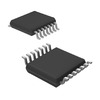
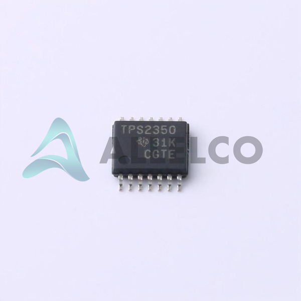
TPS2350PWR
Manufacturer
Texas Instruments
Introduction
The TPS2350PWR is a Hot Swap Controller designed for managing power distribution and inrush current in high-availability systems.
Product Features and Performance
Hot Swap Controller for power management
Supports 3 independent channels
Does not include an internal switch
Features Auto Retry for fault management
Programmable for Current Limit, Fault Timeout, Over Voltage Protection (OVP), Slew Rate, Under Voltage Lockout (UVLO)
Designed for use with -48V systems
Can operate with supply voltages from -80V to -12V
Product Advantages
Flexible programmability for various system requirements
Supports a wide range of supply voltages for diverse applications
High level of integration to minimize external component count
TPS2350PWR (2)
Key Technical Parameters
Number of Channels: 3
Programmable Features: Current Limit, Fault Timeout, OVP, Slew Rate, UVLO
Voltage Supply: -80V ~ -12V
Operating Temperature: -40°C ~ 85°C
Quality and Safety Features
Auto Retry ensures fault recovery and system reliability
OVP and UVLO for protecting against voltage irregularities
Compatibility
Compatible with systems requiring -48V supply voltage
Mounts via Surface Mount technology
Application Areas
Telecom and Networking Equipment
Server and Storage Systems
High-Availability Industrial Applications
Product Lifecycle
Active status, with no current indication of discontinuation
Compatible replacements or upgrades may be offered
Several Key Reasons to Choose This Product
Texas Instruments, a trusted industry leader in Power Management ICs
High flexibility and programmability for system optimization
Wide operating temperature range suitable for harsh environments
Robust feature set for protection and safety of power systems
Suitable for high-availability and mission-critical applications

 TPS2350DRTexas InstrumentsIC HOT SWAP CTRLR -48V 14SOIC
 TPS23523EVM-863Texas InstrumentsTPS23523EVM-863
 TPS23525EVM-815Texas InstrumentsTPS23525EVM-815
 TPS23521EVM-001Texas InstrumentsEVAL BOARD FOR TPS23521
 TPS2350EVMTexas InstrumentsEVAL MODULE FOR TPS2350
 TPS2350DRG4Luminary Micro / Texas InstrumentsIC MANAGER POWER HOTSWAP 14-SOIC


