TPS54623RHLR (1)
Manufacturer Part Number
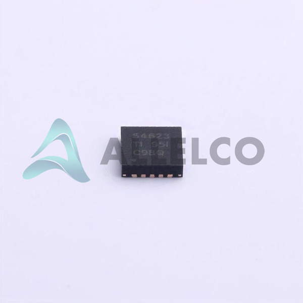
TPS54623RHLR
Manufacturer
Texas Instruments
Introduction
The TPS54623RHLR is a highly efficient, adjustable output, step-down buck converter from Texas Instruments. It is part of the SWIFT™ series, designed for power management in various electronic applications.
Product Features and Performance
Adjustable output voltage ranging from 0.6V to 15V
Supports input voltages from 4.5V to 17V
Can deliver output current up to 6A
Features a synchronous rectifier to improve efficiency
Switching frequency is adjustable from 200kHz to 1.6MHz
High-temperature operational reliability from -40°C to 150°C
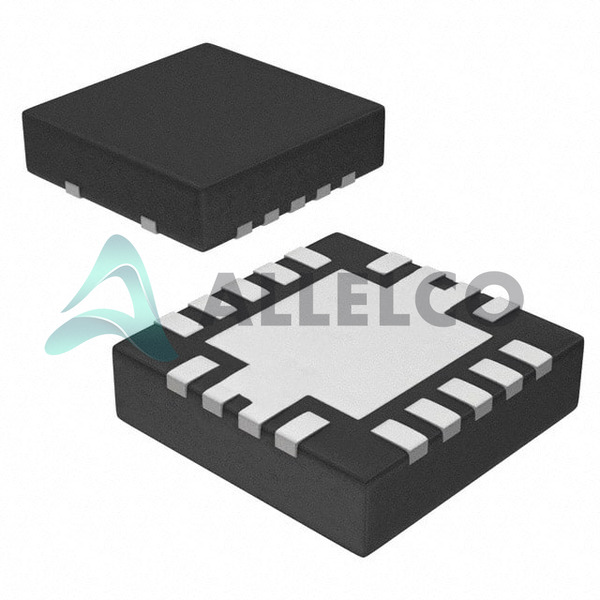
Available in a compact 14-VFQFN exposed pad package
Product Advantages
High efficiency and reliability for power regulation
Versatile input and output voltage ranges support various applications
Adjustable switching frequency allows flexibility in design
Compact form factor suitable for space-constrained applications
TPS54623RHLR (2)
Key Technical Parameters
Input Voltage: 4.5V Min, 17V Max
Output Voltage: 0.6V Min, 15V Max
Output Current: 6A
Switching Frequency: 200kHz ~ 1.6MHz
Operating Temperature Range: -40°C ~ 150°C
Mounting Type: Surface Mount
Quality and Safety Features
Built with over-temperature and over-current protections
Compliant with industry safety and quality standards
Compatibility
Suitable for use in conjunction with a wide range of electronic components and systems due to its flexible input and output configurations
Application Areas
Telecommunications
Consumer Electronics
Computing Systems
Industrial Equipment
Product Lifecycle
Currently active in the Texas Instruments product lineup
Not nearing discontinuation as of now
Upgrades and replacement options are available and continuously supported by Texas Instruments
Several Key Reasons to Choose This Product
Highly efficient power management capability enhances device performance and longevity
Supports a wide range of input and output specifications catering to various electronic applications
High reliability under extreme temperature conditions ensures operational stability
Compact and versatile design fits well in different system architectures
Continuous support and availability from Texas Instruments, a reputable manufacturer in the semiconductor industry

 TPS54626PWPRTexas InstrumentsIC REG BUCK ADJ 6.5A 14HTSSOP
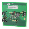 TPS54622EVM-012Texas InstrumentsEVAL MODULE FOR TPS54622-012
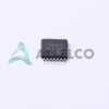 TPS54625PWPTexas InstrumentsIC REG BUCK ADJ 6.5A 14HTSSOP
 TPS54626PWPTexas InstrumentsIC REG BUCK ADJ 6.5A 14HTSSOP
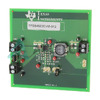 TPS54623EVM-012Texas InstrumentsEVAL MODULE FOR TPS54623-012
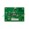 TPS54626EVM-608Texas InstrumentsEVAL MODULE FOR TPS54626
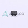 TPS54627DDATexas InstrumentsIC REG BUCK ADJUSTABLE 6A 8SOPWR
 TPS54625EVM-608Texas InstrumentsEVAL MODULE FOR TPS54625


