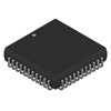
View All

Please refer to the English Version as our Official Version.Return

Europe
France(Français) Germany(Deutsch) Italy(Italia) Russian(русский) Poland(polski) Czech(Čeština) Luxembourg(Lëtzebuergesch) Netherlands(Nederland) Iceland(íslenska) Hungarian(Magyarország) Spain(español) Portugal(Português) Turkey(Türk dili) Bulgaria(Български език) Ukraine(Україна) Greece(Ελλάδα) Israel(עִבְרִית) Sweden(Svenska) Finland(Svenska) Finland(Suomi) Romania(românesc) Moldova(românesc) Slovakia(Slovenská) Denmark(Dansk) Slovenia(Slovenija) Slovenia(Hrvatska) Croatia(Hrvatska) Serbia(Hrvatska) Montenegro(Hrvatska) Bosnia and Herzegovina(Hrvatska) Lithuania(lietuvių) Spain(Português) Switzerland(Deutsch) United Kingdom(English)
Asia/Pacific
Japan(日本語) Korea(한국의) Thailand(ภาษาไทย) Malaysia(Melayu) Singapore(Melayu) Vietnam(Tiếng Việt) Philippines(Pilipino)
Africa, India and Middle East
United Arab Emirates(العربية) Iran(فارسی) Tajikistan(فارسی) India(हिंदी) Madagascar(malaɡasʲ)
South America / Oceania
New Zealand(Maori) Brazil(Português) Angola(Português) Mozambique(Português)
North America
United States(English) Canada(English) Haiti(Ayiti) Mexico(español)
HomeProductsIntegrated Circuits (ICs)Embedded - MicrocontrollersATMEGA8535L-8JI
Image may be representation.
See specifications for product details.
EXPRESS OPTION
Payment method

ATMEGA8535L-8JI - Microchip Technology

Manufacturer Part Number
ATMEGA8535L-8JI
Manufacturer
Microchip Technology
Allelco Part Number
32D-ATMEGA8535L-8JI
Warranty
1 Year Allelco Warranty - Find out more
Stock Status:
14,240 pcs available, New & Original
Parts Description
IC MCU 8BIT 8KB FLASH 44PLCC
Package
44-PLCC (16.6x16.6)
Data sheet
ATMEGA8535L-8JI.pdf
RoHs Status
 
Our certification
In stock: 14240

Required fields are indicated by an asterisk (*)
Please send RFQ, we will respond immediately.

Quantity

Specifications

ATMEGA8535L-8JI Tech Specifications
Microchip Technology - ATMEGA8535L-8JI technical specifications, attributes, parameters and parts with similar specifications to Microchip Technology - ATMEGA8535L-8JI

Product Attribute Attribute Value
Manufacturer Microchip Technology
Voltage - Supply (Vcc/Vdd) 2.7V ~ 5.5V
Supplier Device Package 44-PLCC (16.6x16.6)
Speed 8MHz
Series AVR® ATmega
RAM Size 512 x 8
Program Memory Type FLASH
Program Memory Size 8KB (4K x 16)
Peripherals Brown-out Detect/Reset, POR, PWM, WDT
Package / Case 44-LCC (J-Lead)
Package Tube
Product Attribute Attribute Value
Oscillator Type Internal
Operating Temperature -40°C ~ 85°C (TA)
Number of I/O 32
Mounting Type Surface Mount
EEPROM Size 512 x 8
Data Converters A/D 8x10b
Core Size 8-Bit
Core Processor AVR
Connectivity I²C, SPI, UART/USART
Base Product Number ATMEGA8535

Environmental & Export Classifications

ATTRIBUTE DESCRIPTION
RoHs Status RoHS non-compliant
Moisture Sensitivity Level (MSL) 2 (1 Year)
REACH Status REACH Unaffected
ECCN EAR99
HTSUS 8542.31.0001

Frequently Asked Questions(FAQ)

How does the ATMEGA8535L-8JI compare to other AVR microcontrollers in terms of program memory capacity and voltage range when used in low-power battery-operated designs?
The ATMEGA8535L-8JI offers 8KB of FLASH program memory, which is suitable for moderate-complexity embedded applications such as sensor data acquisition or control logic with peripheral management. Its operating voltage range of 2.7V to 5.5V provides flexibility for both low-voltage battery systems and standard 5V digital environments. Compared to higher-end models like the ATmega1284P, this device trades increased flash capacity for a more constrained I/O count and RAM size—512 bytes—which may limit multitasking in software-heavy designs. For applications requiring extended battery life, the internal oscillator at 8MHz allows operation without external crystals, reducing component count and power consumption compared to devices needing high-frequency external clocks.
What are the thermal limitations of the ATMEGA8535L-8JI when deployed in industrial environments, and how might these affect long-term reliability in compact enclosures?
The ATMEGA8535L-8JI is rated for an operating temperature range of -40°C to 85°C, making it suitable for most industrial control systems and automotive edge applications. However, in densely populated PCBs or sealed enclosures with limited airflow, sustained high ambient temperatures near 85°C could push junction temperatures beyond safe limits if thermal resistance is not properly managed. Since the package is a 44-PLCC (16.6x16.6 mm), it has relatively poor heat dissipation compared to QFN or SOIC alternatives due to its ceramic substrate and limited exposed pads. Designers should account for this by maintaining adequate spacing around the component and avoiding continuous high-current peripheral activity during peak loads to ensure long-term stability.
Can the ATMEGA8535L-8JI reliably drive multiple LED strings or motor control circuits directly from GPIO pins, and what current sourcing considerations apply?
The ATMEGA8535L-8JI provides 32 general-purpose I/O pins, each capable of sourcing up to 40mA under typical 5V conditions, though the total device current must remain within absolute maximum ratings (typically 200mA for all I/O combined). While individual pins can briefly handle short bursts above 20mA, driving multiple high-brightness LEDs or inductive loads like small DC motors directly from GPIOs risks exceeding thermal and electrical limits. In such cases, external MOSFETs or driver ICs are recommended. For example, a single pin driving a 30mA LED string may operate safely, but parallel strings across several pins could quickly violate aggregate current constraints unless buffered externally.
Is the internal oscillator of the ATMEGA8535L-8JI sufficiently accurate for applications requiring precise timing, such as UART baud rate generation or PWM synchronization?
The ATMEGA8535L-8JI uses an internal RC oscillator calibrated to 8MHz with a typical accuracy of ±10% over temperature and voltage variations. This level of precision is generally acceptable for basic UART communication at standard baud rates (e.g., 9600 or 115200) using built-in calibration registers, but may introduce timing drift in critical applications like real-time clock generation or synchronous motor control where jitter accumulates over time. Compared to crystal-based oscillators, which offer ±20 ppm accuracy, the internal oscillator is less reliable for high-fidelity timing. Therefore, for mission-critical timing tasks, an external 16MHz crystal with PLL support would be preferable despite added PCB complexity.
How does the EEPROM size of the ATMEGA8535L-8JI impact firmware update strategies in field-deployed devices, and what write endurance should engineers assume?
With 512 x 8 bits of on-chip EEPROM, the ATMEGA8535L-8JI supports persistent configuration storage such as calibration values, user preferences, or boot counters. Each EEPROM byte can endure approximately 100,000 write cycles before degradation, so frequent updates (e.g., every second) will lead to premature failure. Engineers should implement wear-leveling algorithms or store only infrequently changed data in EEPROM, while reserving RAM for runtime variables. Compared to larger AVR models with 4KB EEPROM, this device demands careful resource planning in data logging or telemetry applications where state persistence is required between power cycles.
What trade-offs exist between using the ATMEGA8535L-8JI in SPI versus I2C mode for interfacing with external sensors, and how do pin usage differ?
The ATMEGA8535L-8JI supports both SPI and I2C peripherals simultaneously, but they share certain pins depending on the port mapping. SPI typically requires four dedicated lines (MOSI, MISO, SCK, SS), consuming three I/O pins plus one chip select per slave. I2C uses only two bidirectional lines (SDA, SCL), saving I/O resources but limiting scalability. In tight pin-count designs, SPI may be preferred for fast point-to-point communication with minimal overhead, whereas I2C enables daisy-chaining multiple devices. However, since the ATMEGA8535 has limited RAM, managing multiple active peripherals concurrently requires careful memory allocation to avoid buffer overflows during high-speed data transfers.
Can the ATMEGA8535L-8JI be used in safety-critical systems requiring brown-out detection, and how responsive is its reset circuitry under voltage sags?
Yes, the ATMEGA8535L-8JI includes programmable brown-out detection (BOD) that triggers a reset when Vcc drops below configurable thresholds (e.g., 2.7V, 4.3V). This feature prevents erratic behavior during power-up transients or brownouts, enhancing system robustness. The BOD response time is typically tens of milliseconds, allowing the MCU to stabilize before resuming operation. However, during rapid voltage dips lasting less than this window, the MCU may not reset promptly. For applications like medical devices or automotive controls, additional external voltage supervisors may be warranted to complement the internal BOD and meet functional safety standards.
How does the absence of RoHS compliance affect procurement and end-of-life planning for projects using the ATMEGA8535L-8JI in consumer electronics?
As the ATMEGA8535L-8JI is marked RoHS non-compliant, it contains restricted substances such as lead in the solder balls or packaging materials, which may disqualify it from use in EU-based consumer products after July 2021. This affects supply chain continuity and regulatory certification processes. Projects targeting global markets must verify alternate sourcing or consider newer AVR variants like the ATmega328P, which are RoHS compliant. Additionally, lead-free assembly processes cannot be used with this part, potentially increasing manufacturing costs or limiting foundry options. Engineers should factor in obsolescence risk when selecting legacy components for long-lifecycle designs.
What is the expected start-up time for the ATMEGA8535L-8JI after power-on, and how does it impact system initialization sequences?
Upon power-up, the ATMEGA8535L-8JI requires approximately 6–8 clock cycles for the internal oscillator to stabilize, followed by the Power-On Reset (POR) delay of up to 14 clock cycles. At 8MHz, this results in a startup delay of about 2 microseconds. While this is sufficient for most applications, real-time systems requiring sub-millisecond responsiveness may need explicit delays in firmware before enabling peripherals. Unlike external-crystal-based MCUs with longer warm-up times, the internal oscillator allows faster boot, but designers must still respect the full POR sequence to ensure correct register states and avoid race conditions during peripheral initialization.
How should interrupt latency be accounted for in time-sensitive routines when using the ATMEGA8535L-8JI, and what factors influence response time?
The ATMEGA8535L-8JI typically responds to interrupts within 4 clock cycles once acknowledged, assuming no nested interrupts or context-saving overhead. However, if the CPU is executing a multi-cycle instruction (e.g., division or multiplication), the actual latency increases accordingly. Additionally, global interrupt flags must be enabled via the GIE bit. In practice, worst-case interrupt latency can reach several microseconds at 8MHz. For applications requiring deterministic response—such as encoder input capture or pulse-width measurement—engineers should minimize critical section durations and avoid disabling interrupts unnecessarily. Using dedicated hardware peripherals (e.g., Timer/Counter in input capture mode) reduces software overhead compared to polling loops.
What programming interface options are available for the ATMEGA8535L-8JI, and which tools are compatible with its 44-PLCC packaging?
The ATMEGA8535L-8JI supports in-system programming (ISP) via the SPI interface using standard 6-wire protocols. Compatible programmers include Atmel Studio with AVR Dragon or USBasp clones, provided they support PLCC socket adapters. Due to the J-lead configuration, direct pin access is challenging without a breakout board; thus, many developers use PLCC-to-DIP adapters for breadboard prototyping. Unlike QFN packages, the PLCC variant allows easier manual probing during debugging. Note that parallel programming modes are not supported, so only serial ISP is viable for firmware updates post-deployment.
How does the ATMEGA8535L-8JI compare to the ATmega8L in terms of power consumption and feature set for portable IoT endpoints?
The ATMEGA8535L-8JI improves upon the older ATmega8L by offering enhanced peripherals including USART, I2C, SPI, and an 8-channel ADC, whereas the ATmega8L lacks USART and has fewer timers. In sleep mode, both consume similar current (~1µA with BOD disabled), but the ATMEGA8535L-8JI’s additional features increase active current slightly—around 0.6mA at 1MHz and 3V. However, its broader connectivity suite makes it better suited for modern IoT nodes requiring sensor networking without external logic. Despite similar flash sizes (8KB vs. 8KB), the ATMEGA8535L-8JI provides more flexible I/O mapping and watchdog timer configurations, justifying its use in evolving designs even at the cost of marginally higher quiescent draw.
Can the ATMEGA8535L-8JI operate reliably in environments with electromagnetic interference (EMI), and what layout practices reduce susceptibility?
While the ATMEGA8535L-8JI itself lacks specialized EMI hardening, its performance depends heavily on PCB layout. Proximity to switching regulators, long unshielded traces, or poor grounding can induce noise into the 10-bit ADC or corrupt UART traffic. To mitigate this, designers should keep analog and digital grounds separate, place decoupling capacitors (100nF ceramic) close to Vcc pins, and minimize loop areas on clock lines. Since the device runs at 8MHz, conducted emissions are generally low, but radiated interference from nearby RF sources may require ferrite beads or shielding in industrial settings. Proper bypassing and short return paths significantly improve resilience compared to unoptimized layouts.
What happens if the ATMEGA8535L-8JI exceeds its maximum junction temperature during operation, and how can thermal modeling inform design choices?
Exceeding the maximum junction temperature (typically 150°C) causes immediate degradation of transistor performance, increased leakage current, and potential latch-up. Even brief exposure near 100°C can accelerate electromigration in metal interconnects, shortening mean time between failures. Thermal modeling using the package’s θJA (junction-to-ambient thermal resistance, ~35°C/W for PLCC) helps estimate steady-state temperatures under worst-case load. For example, dissipating 2W continuously would raise the junction by 70°C above ambient—potentially reaching unsafe levels in enclosed spaces. Thus, engineers should simulate worst-case power profiles and add heatsinking or reduce duty cycle where feasible to maintain reliability margins.
Is it possible to upgrade firmware in the ATMEGA8535L-8JI without removing it from the circuit, and what precautions are necessary?
Yes, the ATMEGA8535L-8JI supports in-circuit serial programming (ICSP), allowing firmware updates while mounted on the PCB. However, care must be taken to isolate sensitive signals during programming—especially RESET and MOSI lines—from conflicting drivers. Many boards implement pull-up resistors on ICSP headers to prevent floating inputs. Additionally, brown-out protection should be disabled temporarily during erase/write operations to avoid premature resets. After programming, re-enabling BOD ensures continued voltage monitoring. This capability simplifies field updates but requires robust PCB routing to avoid noise coupling into the programming interface.
How does the 44-PLCC package of the ATMEGA8535L-8JI influence mechanical stress tolerance compared to surface-mount alternatives like QFN?
The 44-PLCC (plastic leaded chip carrier) package uses ceramic construction with J-shaped leads, providing moderate mechanical strength and ease of hand-soldering or socket mounting. It resists bending better than fine-pitch QFNs, making it ideal for prototyping or modular designs where repeated insertion occurs. However, under vibration or thermal cycling, the brittle ceramic base can crack if subjected to excessive force or rapid temperature changes beyond -40°C to 85°C. In contrast, plastic quad flat packs (PQFP) offer superior solder joint fatigue resistance but harder to inspect visually. For rugged industrial installations, conformal coating and strain relief are advisable to protect the ATMEGA8535L-8JI’s PLCC form factor.
What role does the Watchdog Timer play in ensuring recovery from software hangs in ATMEGA8535L-8JI-based systems?
The integrated Watchdog Timer (WDT) automatically resets the ATMEGA8535L-8JI if the software fails to clear it within a programmed interval (ranging from 16ms to 8s). This is crucial in bare-metal or RTOS-less environments where infinite loops or pointer corruption can leave the system unresponsive. By periodically feeding the dog in main(), engineers enable graceful recovery without manual intervention. However, improper WDT usage (e.g., clearing it too late) may cause unnecessary resets. In safety-critical code, pairing the WDT with stack monitoring or heartbeat signals enhances fault detection beyond basic reset functionality.
Why might someone choose the ATMEGA8535L-8JI over a newer ARM Cortex-M0 despite its lower processing headroom, and what niche advantages does it offer?
Although the ATMEGA8535L-8JI operates on an 8-bit AVR core with only 8KB flash and 512B RAM, its simplicity, deterministic execution, and proven ecosystem make it attractive for legacy upgrades or ultra-low-cost embedded systems. Unlike ARM MCUs, it consumes negligible static power, boots instantly, and integrates peripherals natively without complex drivers. Its compatibility with existing AVR toolchains and libraries reduces development time in retrofitting older designs. Furthermore, the 44-PLCC package facilitates drop-in replacements in legacy sockets, offering a migration path without redesigning PCBs. For non-graphical, event-driven applications where throughput is secondary to reliability and footprint, the ATMEGA8535L-8JI remains a pragmatic choice despite architectural limitations.

Parts with Similar Specifications

The three parts on the right have similar specifications to Microchip Technology ATMEGA8535L-8JI

Product Attribute ATMEGA8535L-8JI ATMEGA8535L-8MJ ATMEGA8535L-8JC ATMEGA8535L-8AI
Part Number ATMEGA8535L-8JI ATMEGA8535L-8MJ ATMEGA8535L-8JC ATMEGA8535L-8AI
Manufacturer Atmel Microchip Technology Microchip Technology Atmel
Number of I/O - - - -
Base Product Number - DAC34H84 MAX500 ADS62P42
Package / Case - 196-LFBGA 16-DIP (0.300', 7.62mm) 64-VFQFN Exposed Pad
Core Size - - - -
Supplier Device Package - 196-NFBGA (12x12) 16-PDIP 64-VQFN (9x9)
Mounting Type - Surface Mount Through Hole Surface Mount
EEPROM Size - - - -
Package - Tape & Reel (TR) Tube Tape & Reel (TR)
Oscillator Type - - - -
Operating Temperature - -40°C ~ 85°C 0°C ~ 70°C -40°C ~ 85°C
Peripherals - - - -
Speed - - - -
RAM Size - - - -
Data Converters - - - -
Voltage - Supply (Vcc/Vdd) - - - -
Core Processor - - - -
Series - - - -
Program Memory Size - - - -
Connectivity - - - -
Program Memory Type - - - -

ATMEGA8535L-8JI Datasheet PDF

Download ATMEGA8535L-8JI pdf datasheets and Microchip Technology documentation for ATMEGA8535L-8JI - Microchip Technology.

Datasheets
ATMEGA8535(L) Complete.pdf
HTML Datasheet
Cylindrical Battery Holders.pdf
PCN Packaging
MBB/Label Chgs 16/Nov/2018.pdf Transfer to Microchip/Label/Pkg 5/Sep/2016.pdf

Customer Reviews

Evaluation: 10 Articles

  • Dani***alkerTech
    Jun 1, 2026

    Product works, but setup took more effort than expected. Once configured the MCU ran reliably, although documentation support felt older compared with newer platforms. Fine for maintenance projects.

  • Yuki***aka88
    May 26, 2026

    信号通信プロジェクトでこのRS-485トランシーバーを使用しました。設置は簡単で、長距離ケーブルでも通信は安定していました。消費電力も、以前使用していたものより低くなっています。

  • Stev***aker
    May 20, 2026

    Solid diode for power rectification. Works well in switching circuits.

  • Bran***Lewis
    May 11, 2026

    Compact FPGA with good performance. Suitable for basic signal processing tasks.

  • Oliv***arris
    May 7, 2026

    Reliable I/O expander. Works well in embedded control applications.

  • Jess***Jones
    Apr 17, 2026

    It offers good value for the price, and the specifications match the description. I’ve been using it for two days with no issues, and I’ll definitely buy it again if I need it in the future.

  • Mich***Smith
    Apr 17, 2026

    Shipping was on time, the component pins are neatly aligned, and I tested 10 of them with a multimeter—all readings were within the specified range. Highly recommended.

  • Aman***arris
    Apr 3, 2026

    It was great—the entire process, from placing the order to receiving the package, went very smoothly. The components were consistent, the price was fair, and I had a very pleasant shopping experience.

  • Mike***nch
    Apr 3, 2026

    Better than expected! The resistance and capacitance readings were spot-on, and it passed the test on the first try. The service was reliable, and the packaging was thoughtful—I highly recommend it.

  • Daic***K.
    Mar 23, 2026

    Very good. No issue after long time testing.

Write a Review

Your Email address will not be published.

Shipment

Delivery Time

In-stock items can be shipped within 24 hours. Some parts will be arranged for delivery within 1-2 days from the date all items arrive at our warehouse. And Allelco ships order once a day at about 17:00, except Sunday. Once the goods are shipped, the estimated delivery time depends on the shipping methods and Delivery destination. The table below shows are the logistic time for some common countries.

Delivery Cost

  1. Use your express account for shipment if you have one.
  2. Use our account for the shipment. Refer to the table below for the approximate charges.
(Different time frame / countries / package size has different price.)

Delivery Method

  1. Global Common Shipment by DHL / UPS / FedEx / TNT / EMS / SF we support.
  2. Others more shipping ways, please get in touch with your customer manager.

Common Countries Logistic Time Reference
Region Country Logistic Time(Day)
America United States 5
Brazil 7
Europe Germany 5
United Kingdom 4
Italy 5
Oceania Australia 6
New Zealand 5
Asia India 4
Japan 4
Middle East Israel 6
DHL & FedEx Shipment Charges Reference
Shipment charges(KG) Reference DHL(USD$)
0.00kg-1.00kg USD$30.00 - USD$60.00
1.00kg-2.00kg USD$40.00 - USD$80.00
2.00kg-3.00kg USD$50.00 - USD$100.00
Note:
The above table is for reference only. There may have some data bias for the uncontrollable factors.
Contact us if you have any questions.
  • QC (Quality Warranty)
  • Payment Support
  • Packaging
  • Certifications & Memberships

QC (Quality Warranty)

Allelco is committed to exceeding customer expectations through customer service excellence, order accuracy, and on-time delivery.
This is achieved through our commitment to the continual improvement of our processes, services, and products.


Strict quality inspection builds a solid foundation for electronic component quality.
  1. Visual inspection
  2. Performance testing and reliability verification
  3. Standardized full-process testing
  4. Precise control of every parameter
We eliminate defective components and ensure the stable operation of electronic devices through professional quality standards.

Payment Support

The payment method can be chosen from the methods shown below: Wire Transfer (T/T, Bank Transfer), Western Union, Credit card, PayPal.
  • HKBea
  • Paypal
  • MasterCard
  • Western-Union
  • VISA
Stable Delivery, Sincere Partnership — Your Faithful Supply Chain Partner
  • Efficient Supply Management
  • Cost-Saving Procurement
  • Fast Sourcing & Delivery
Contact us if you have any questions.

Packaging

Electrostatic Discharge Protection and Handling

All electrostatic-sensitive components are handled in accordance with electrostatic discharge control procedures. The products are hermetically sealed in anti-static safe packaging to prevent electrostatic damage. Appropriate labeling is also applied for identification and traceability. This ensures product integrity during storage, handling and transportation.


ESD

Certifications & Memberships

Third-party certified, strict quality control. Our certification
  • ISO 9001: 2015
  • ISO 13485: 2016
  • ISO 14001: 2015
  • ISO 28000: 2007
  • ISO 45001: 2018
  • GB/T 27922-2011
  • SMTA
  • IPC
  • ESD
  • PSMA
Microchip Technology

ATMEGA8535L-8JI

Microchip Technology
32D-ATMEGA8535L-8JI

Want a better price? Add to Cart and Submit RFQ now, we'll contact you immediately.

0 RFQ
Shopping cart (0 Items)
It is empty.
Compare List (0 Items)
It is empty.
Feedback

Your feedback matters! At Allelco, we value the user experience and strive to improve it constantly.
Please share your comments with us via our feedback form, and we'll respond promptly.
Thank you for choosing Allelco.

Subject
E-mail
Comments
Captcha
Drag or click to upload file
Upload File
types: .xls, .xlsx, .doc, .docx, .jpg, .png and .pdf.
Max file size: 10MB