What Is a Hall Effect Transducer and How It Works
You come across Hall effect sensors in many everyday devices, yet their operation can feel unclear at first. A closer look shows how these sensors respond to magnetic fields and turn that response into a usable electrical signal. As you go through the concepts, you begin to see how current, magnetic fields, and material properties all connect. With simple explanations and practical examples, the topic becomes easier to follow and relate to real circuits and systems you might encounter.Catalog
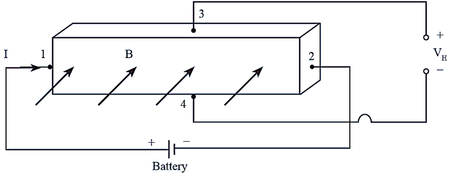
Figure 1. Hall Effect Transducer Diagram
What Is a Hall Effect Transducer
A Hall Effect Transducer is an electronic device that detects a magnetic field and converts it into an electrical signal that can be measured. Its operation is based on the Hall effect, where a current-carrying material develops a small voltage across its sides when exposed to a magnetic field perpendicular to the direction of current flow. Through this effect, the transducer converts magnetic field strength into a measurable electrical output.
This conversion is useful because electrical signals are easier to measure, process, and use in circuits than magnetic fields themselves. The output changes with the applied field, allowing the magnetic condition to be represented as a readable voltage signal. As a result, the transducer provides a direct and effective way to detect magnetic field presence and strength in a form that electronic circuits can use.
Structure and Working Principle of a Hall Effect Transducer
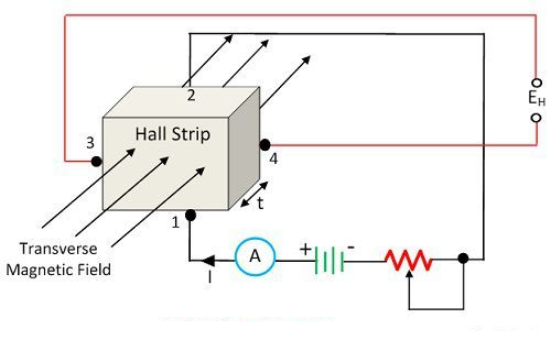
Figure 2. Hall Effect Transducer Structure
A Hall Effect Transducer is built around a thin semiconductor strip with four terminals placed at specific points. One pair of terminals carries the input current through the strip, while the other pair collects the output voltage. The magnetic field is applied across the strip at a right angle to the current path, because this arrangement allows the transducer to produce its electrical output.
During operation, current flows through the semiconductor strip from one side to the other. When no magnetic field is present, the charge carriers move along the current path without creating a noticeable voltage across the output terminals. When a magnetic field is applied perpendicular to that path, the moving charge carriers are pushed sideways and begin to collect along one side of the strip.
This sideways movement of charge creates a difference in electric potential between the output terminals. That difference appears as the Hall voltage, which is the measurable output of the transducer. In this way, the semiconductor strip provides the path for current flow, the magnetic field causes charge deflection, and the output terminals capture the resulting voltage.
Hall Voltage and How It Is Generated
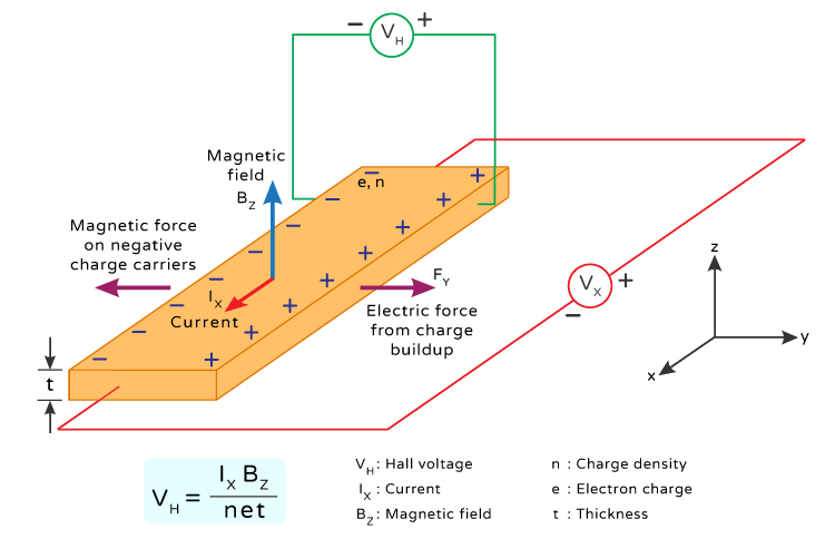
Figure 3. Hall Voltage Generation
Hall voltage is the small voltage that appears across a current-carrying material when a magnetic field is applied perpendicular to the direction of current flow. The field pushes the moving charge carriers sideways, causing them to collect on one side of the material while the opposite side is left with an opposite charge, and this separation of charge creates a difference in electric potential known as Hall voltage.
The size of the Hall voltage depends on the current, the magnetic field strength, the material, and the thickness of the sensing element. It increases as the current or magnetic field becomes larger, and it decreases when the material is thicker in the direction of the field.
A simplified expression for this relationship is VH = (I × B) / (n × e × t), where VH is the Hall voltage, I is the current, B is the magnetic field, n is the charge carrier density, e is the charge of an electron, and t is the thickness of the material. This expression shows the main factors that control the output voltage without adding unnecessary mathematical detail.
Materials Used in Hall Effect Sensors
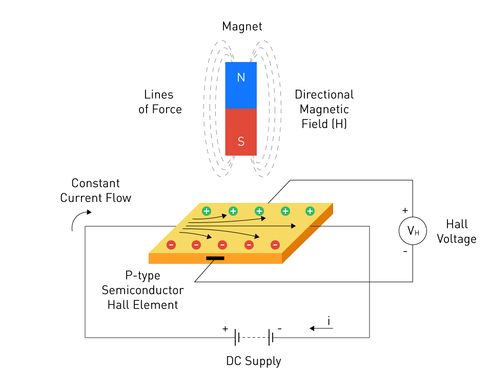
Figure 4. Semiconductor Hall Sensor Setup
Hall Effect devices can be made from both metals and semiconductors, since both can produce a Hall voltage when current flows through them in the presence of a magnetic field. In metals, the effect is usually very small, which makes the output harder to detect and use in sensing applications. For that reason, most Hall Effect devices are made from semiconductor materials rather than ordinary metals.
Semiconductors are commonly preferred because they offer higher sensitivity. This means they produce a larger Hall voltage under the same conditions, making the output easier to measure. A stronger output also helps the device respond more clearly to changes in the magnetic field.
The material used in the sensing element has a direct effect on output voltage and measurement accuracy. Properties such as charge carrier density and material thickness influence how much Hall voltage is produced. Materials that generate a larger and more stable output are generally better suited for accurate measurement.
Types of Hall Effect Sensors
Analog Hall Effect Sensors
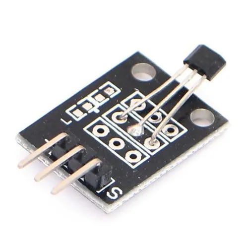
Figure 5. Analog Hall Effect Sensor Module
Analog Hall Effect sensors produce a continuous output voltage that changes in proportion to the applied magnetic field. As the magnetic field becomes stronger or weaker, the output voltage changes with it, allowing the sensor to show gradual variations rather than only a single state. Because the output follows the field continuously, this type of sensor is useful when the circuit needs to measure how much the magnetic field changes, not just whether it is present.
This type is commonly used in position sensing, current sensing, and other measurement tasks where a smooth and readable output is required. It is well suited for precise measurement because even small changes in the magnetic field can appear in the output signal, making fine movement or field variation easier to detect.
Digital Hall Effect Sensors
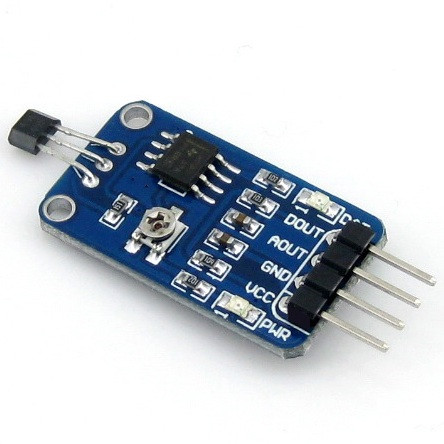
Figure 6. Digital Hall Effect Sensor Module
Digital Hall Effect sensors provide a discrete output, usually an ON or OFF signal, instead of a continuously changing voltage. They operate with an internal switching point, often called a magnetic threshold, so when the magnetic field reaches or passes that level, the output changes state. When the field falls below a defined release level, the output returns to its original state, giving electronic systems a clear and easy-to-read switching signal.
Because they respond to threshold levels rather than gradual field changes, digital Hall Effect sensors are widely used in switching and detection systems. Common applications include door open and close detection, limit switching, proximity sensing, pulse counting, and position detection, where the main purpose is to determine whether a magnetic target has reached a specific point.
Applications of Hall Effect Transducers

Figure 7. Hall Effect Sensor Applications
Hall Effect transducers are widely used for magnetic field sensing in industrial and scientific instruments where accurate field strength measurement is required.
In current sensing applications, they are commonly deployed in motor drives, power supplies, and battery management systems to measure current without direct electrical contact.
For position and displacement detection, these sensors are used in automotive systems, linear actuators, and robotics, where changes in magnetic field indicate movement.
They are also applied in power monitoring systems, combining current and voltage data to estimate real-time power consumption in electrical equipment.
Advantages and Disadvantages of Hall Effect Transducers
| Advantages | Limitations |
| Non-contact measurement | Sensitive to temperature drift |
| Galvanic isolation between sensing circuit and current path | Accuracy can be limited in basic open-loop designs |
| Safe measurement of high current levels | Stray magnetic fields can affect readings |
| Very low insertion loss | Lower signal levels may need amplification or conditioning |
| Low power loss and reduced heating | Low-current measurement may require a magnetic core or extra turns |
| Measures AC and DC current | Open-loop versions have moderate bandwidth and response time |
| Good linearity and reliable output in precision devices | Closed-loop versions are larger and more expensive |
| Flexible mechanical placement | Closed-loop versions consume more power from the secondary supply |
| Compact, lightweight options are available | Output voltage can be limited in some closed-loop designs |
| High sensitivity and tight switching thresholds are available | Performance depends on material stability and thermal behavior |
Conclusion
You now have a clear view of how a Hall Effect Transducer works and why it is widely used. The way it converts a magnetic field into a measurable signal makes it useful in many practical situations. You can see how its structure, materials, and operating principle all work together to produce reliable results. From sensing current to detecting position, it offers flexible use in different systems. Understanding these basics helps you recognize where and how these sensors fit into real-world electronics. With this foundation, it becomes easier to explore and apply them in your own projects.
About us
ALLELCO LIMITED
Read more
Quick inquiry
Please send an inquiry, we will respond immediately.
Frequently Asked Questions [FAQ]
1. What does a Hall Effect Transducer measure?
It measures magnetic field strength and converts it into an electrical signal that can be read by a circuit.
2. What is the difference between analog and digital Hall sensors?
Analog sensors give a continuous output that changes with the magnetic field, while digital sensors switch between ON and OFF states based on a set threshold.
3. Why are semiconductors used in Hall sensors?
They produce a stronger output voltage compared to metals, making the signal easier to detect and measure.
4. Can a Hall Effect sensor measure current?
Yes, it can measure current indirectly by detecting the magnetic field around a conductor without touching it.
5. Where are Hall Effect sensors commonly used?
They are used in position sensing, current measurement, proximity detection, and many everyday electronic devices.
Choosing the Right Power Adapter Plug: AC Input and DC Output Guide
on April 10th
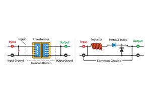
Isolated vs Non-Isolated Power Converters: What’s the Difference?
on April 7th
Popular Posts
-

Complex Instruction Set Computers: How They Changed Computing?
on April 18th 147749
-

USB-C Pinout and Features
on April 18th 111904
-

Using Xilinx Unified Simulation Primitives: A Comprehensive Guide to FPGA Design and Simulation
on April 18th 111349
-

Power Supply Voltages in Electronics: Meaning of VCC, VDD, VEE, VSS, and GND
on April 18th 83714
-

RJ45 Connector Guide: Pinout, Wiring, Cable Types, and Uses
on January 1th 79502
-

The Ultimate Guide to Wire Color Codes in Modern Electrical Systems
The way our electrical systems use colors isn’t just for looks. Each wire color now indicates a specific function, making it easier to identify and handle electrical components correctly during ins...on January 1th 66869
-

Quality (Q) Factor: Equations and Applications
The quality factor, or 'Q', is important when checking how well inductors and resonators work in electronic systems that use radio frequencies (RF). 'Q' measures how well a circuit minimizes energy...on January 1th 63004
-

Purge Valve Guide: Function, Symptoms, Testing, and Replacement for Optimal Engine Performance
The purge valve is a key part of a car’s system that helps keep the air clean by managing fuel vapors before they can escape into the atmosphere. This not only helps the environment by reducing pol...on January 1th 62942
-

Achieving Peak Performance with the Maximum Power Transfer Theorem
The Maximum Power Transfer Theorem explains how energy from a source, such as a battery or generator, flows to a connected load. It shows the exact condition where the load receives the most power....on January 1th 54076
-

A23 Battery Specifications and Compatibility
The A23 battery is a small, cylinder-shaped battery with high voltage. Also called 23A, 23AE, or MN21, it runs at 12 volts and much higher than AA or AAA batteries. Its special design make...on January 1th 52087
HOT Part Number
-
LTC4063EDD#TRPBF
Analog Devices Inc.
IC BATT CHG LI-ION 1CELL 10DFN
MIMX8MM1CVTKZAA
NXP USA Inc.
IC MPU I.MX 8M MINI SOLOLITE
APDS-9005-020
Broadcom Limited
SENSOR OPT 500NM AMB 6CHIPLED
06031A820KAT2A
KYOCERA AVX
CAP CER 82PF 100V C0G/NP0 0603
ICM-20602
TDK InvenSense
IMU ACCEL/GYRO/TEMP I2C/SPI LGA
170M4611
Eaton - Bussmann Electrical Division
FUSE SQUARE 350A 700VAC RECT
08053C105JAZ2A
KYOCERA AVX
CAP CER 1UF 25V X7R 0805
EP1C12F324C6N
Intel
IC FPGA 249 I/O 324FBGA
2SC4617T1G
onsemi
TRANS NPN 50V 0.1A SC75 SOT416
TL431AILPRAG
onsemi
IC VREF SHUNT ADJ 1% TO92-3
ADAU1787BCBZRL
Analog Devices Inc.
4 ADC, 2 DAC LOW POWER CODEC, AU
74VHC164MTCX
onsemi
IC SHIFT REGISTER 8BIT 14TSSOP
DAN222M3T5G
onsemi
DIODE ARRAY GP 80V 100MA SOT723
NR3015T470M
Taiyo Yuden
FIXED IND 47UH 300MA 1.608OHM SM
MM3Z18VC
onsemi
DIODE ZENER 18V 200MW SOD323F
1N4001W
Rectron USA
DIODE GEN 1A 50V SOD-123F
SMBJ90A
Taiwan Semiconductor Corporation
TVS DIODE 90VWM 146VC DO214AA
NTA1215MC
Murata Power Solutions Inc.
DC DC CONVERTER +/-15V 1W -
SDR1307-101KL
Bourns Inc.
FIXED IND 100UH 1.9A 180MOHM SMD
AOT5B65M1
Alpha & Omega Semiconductor Inc.
IGBT 650V 5A TO220
STP16CP596B1R
STMicroelectronics
IC LED DRIVER LINEAR 50MA 24DIP
AD7895ANZ-2
Analog Devices Inc.
IC ADC 12BIT SAR 8DIP
MURB1620CTT4G
onsemi
DIODE ARRAY GP 200V 8A D2PAK
STGIPS30C60T-H
STMicroelectronics
MOD IPM SLLIMM 30A 600V 25SDIP
IXDN604SIA
IXYS Integrated Circuits Division
IC GATE DRVR LOW-SIDE 8SOIC
CY7C63743-SC
Infineon Technologies
IC MCU 8K LS USB/PS-2 24-SOIC
U2745B-MFBG3
Microchip Technology
RF TX IC UHF 310-440MHZ 16LSSOP
DSPIC30F4013T-30I/PT
Microchip Technology
IC MCU 16BIT 48KB FLASH 44TQFP
ADF4106BRUZ-RL
Analog Devices Inc.
IC CLK/FREQ SYNTH 16TSSOP
EL8403IS
Elantec
IC OPAMP GP 4 CIRCUIT 14SOIC
8A35001B-001AJG
Renesas Electronics America Inc
NETWORK TIMING
GRM0337U1HR90BD01D
Murata Electronics
CAP CER 0.9PF 50V U2J 0201
LT1356CS#PBF
Analog Devices Inc.
IC VOLTAGE FEEDBACK 2 CIRC 16SO
AON7280
Alpha & Omega Semiconductor Inc.
MOSFET N-CH 80V 20A/50A 8DFN
IRLI540N
Infineon Technologies
MOSFET N-CH 100V 23A TO220AB FP
VI-J6Z-MZ
Vicor Corporation
VI-J6Z-MZ 300V 2V 5A -
LMH6722MA
Texas Instruments
IC AMP CURRENT FEEDBACK 14SOIC
HZM6.8Z4MWATL-E
Renesas Electronics America Inc
TVS DIODE 3.5VWM 3MPAK
LM4041DIM7-1.2
Texas Instruments
IC VREF SHUNT 1% SC70-5
RT6200GE
Richtek USA Inc.
IC REG BUCK ADJ 600MA SOT23-6
R5F21274SNFP#X6
Renesas Electronics America Inc
IC MCU 16BIT 16KB FLASH 32LQFP
1N5227B
onsemi
DIODE ZENER 3.6V 500MW DO35
12102C472JAT2A
KYOCERA AVX
CAP CER 4700PF 200V X7R 1210
PZTA64
Fairchild Semiconductor
SMALL SIGNAL BIPOLAR TRANSISTOR,
XC1765ELSO8C
AMD
IC PROM SER C-TEMP 3.3V 8-SOIC
XR88C92CJ-F
MaxLinear, Inc.
IC UART FIFO DUAL 44PLCC
RT24C2X202
Bourns, Inc.
TRIMMER 2K OHM 0.75W PC PIN SIDE
DLW31SN900SQ2L
Murata Electronics
CMC 370MA 2LN 90 OHM SMD
LMK432F476ZM-T
Taiyo Yuden
CAP CER 47UF 10V Y5V 1812
MOC207R1VM
onsemi
OPTOISO 2.5KV TRANS W/BASE 8SOIC
GRM0335C1E390JD01D
Murata Electronics
CAP CER 39PF 25V C0G/NP0 0201
SE10PG-M3/84A
Vishay General Semiconductor - Diodes Division
DIODE GEN PURP 400V 1A DO220AA
RABS15M REG
Taiwan Semiconductor Corporation
BRIDGE RECT 1P 1KV 1.5A ABS-L
PI74LPT16245AEX
Diodes Incorporated
IC TXRX NON-INVERT 3.6V 48TSSOP