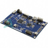
 ATMEGA1284P-XPLDMicrochip TechnologyMEGA-1284P XPLAINED ATMEGA1284P
 ATMEGA1284P-MURMicrochip TechnologyIC MCU 8BIT 128KB FLASH 44VQFN
 ATMEGA1284RFR2-ZURMicrochip TechnologyIC RF TXRX+MCU 802.15.4 48VFQFN
 ATMEGA1284P-MUAtmelIC MCU 8BIT 128KB FLASH 44VQFN
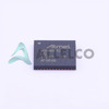 ATMEGA1284RFR2-ZUMicrochip
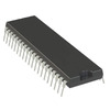 ATMEGA1284-PUMicrochip TechnologyIC MCU 8BIT 128KB FLASH 40DIP
 ATMEGA1284PR231-MUMicrochip TechnologyIC RF TXRX+MCU 802.15.4 44QFN
 ATMEGA1284P-AURMicrochip TechnologyIC MCU 8BIT 128KB FLASH 44TQFP
 ATMEGA1284P-PUMicrochip TechnologyIC MCU 8BIT 128KB FLASH 40DIP
 ATMEGA1284P-AUMicrochip TechnologyIC MCU 8BIT 128KB FLASH 44TQFP
 ATMEGA1284PMUAtmel
 ATMEGA1284PMicrel / Microchip Technology
- Dani***alkerTech
- Jun 1, 2026

Image may be representation.
See specifications for product details.
See specifications for product details.
- EXPRESS OPTION
- Payment method
ATMEGA1284PAU - Atmel
- Manufacturer Part Number
- ATMEGA1284PAU
- Manufacturer
- Atmel
- Allelco Part Number
- 41D-ATMEGA1284PAU
- Warranty
- 1 Year Allelco Warranty - Find out more
- Stock Status:
- 16,300 pcs available, New & Original
- Parts Description
- -
- Data sheet
- -
- Category
- Integrated Circuits (ICs) > Specialized ICs
- RoHs Status
- Our certification
- In stock: 16300


