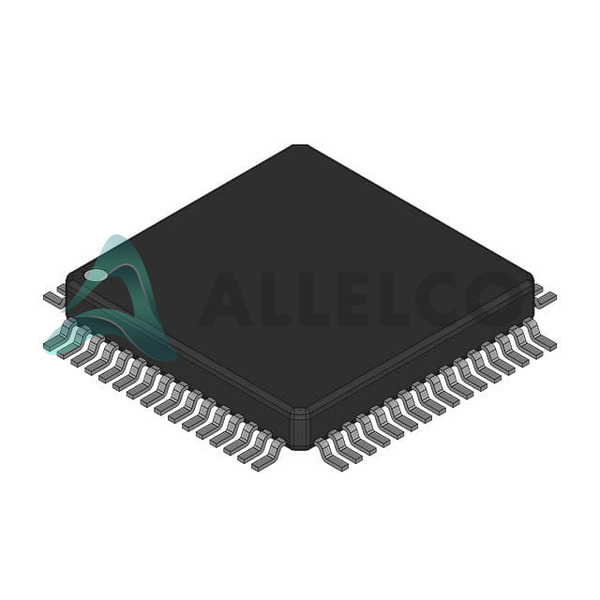
View All

Please refer to the English Version as our Official Version.Return

Europe
France(Français) Germany(Deutsch) Italy(Italia) Russian(русский) Poland(polski) Czech(Čeština) Luxembourg(Lëtzebuergesch) Netherlands(Nederland) Iceland(íslenska) Hungarian(Magyarország) Spain(español) Portugal(Português) Turkey(Türk dili) Bulgaria(Български език) Ukraine(Україна) Greece(Ελλάδα) Israel(עִבְרִית) Sweden(Svenska) Finland(Svenska) Finland(Suomi) Romania(românesc) Moldova(românesc) Slovakia(Slovenská) Denmark(Dansk) Slovenia(Slovenija) Slovenia(Hrvatska) Croatia(Hrvatska) Serbia(Hrvatska) Montenegro(Hrvatska) Bosnia and Herzegovina(Hrvatska) Lithuania(lietuvių) Spain(Português) Switzerland(Deutsch) United Kingdom(English)
Asia/Pacific
Japan(日本語) Korea(한국의) Thailand(ภาษาไทย) Malaysia(Melayu) Singapore(Melayu) Vietnam(Tiếng Việt) Philippines(Pilipino)
Africa, India and Middle East
United Arab Emirates(العربية) Iran(فارسی) Tajikistan(فارسی) India(हिंदी) Madagascar(malaɡasʲ)
South America / Oceania
New Zealand(Maori) Brazil(Português) Angola(Português) Mozambique(Português)
North America
United States(English) Canada(English) Haiti(Ayiti) Mexico(español)
HomeProductsIntegrated Circuits (ICs)Embedded - MicrocontrollersMC908MR16CFUE
MC908MR16CFUE Image
Image may be representation.
See specifications for product details.
EXPRESS OPTION
Payment method

MC908MR16CFUE - Freescale Semiconductor

Manufacturer Part Number
MC908MR16CFUE
Manufacturer
Freescale Semiconductor, Inc. (NXP Semiconductors)
Allelco Part Number
32D-MC908MR16CFUE
Warranty
1 Year Allelco Warranty - Find out more
Stock Status:
15,980 pcs available, New & Original
Parts Description
IC MCU 8BIT 16KB FLASH 64QFP
Package
64-QFP (14x14)
Data sheet
-
RoHs Status
 
Our certification
In stock: 15980

Required fields are indicated by an asterisk (*)
Please send RFQ, we will respond immediately.

Quantity

Specifications

MC908MR16CFUE Tech Specifications
Freescale Semiconductor - MC908MR16CFUE technical specifications, attributes, parameters and parts with similar specifications to Freescale Semiconductor - MC908MR16CFUE

Product Attribute Attribute Value
Manufacturer Freescale Semiconductor, Inc. (NXP Semiconductors)
Voltage - Supply (Vcc/Vdd) 4.5V ~ 5.5V
Supplier Device Package 64-QFP (14x14)
Speed 8MHz
Series HC08
RAM Size 768 x 8
Program Memory Type FLASH
Program Memory Size 16KB (16K x 8)
Peripherals LVD, POR, PWM
Package / Case 64-QFP
Package Bulk
Product Attribute Attribute Value
Oscillator Type Internal
Operating Temperature -40°C ~ 85°C (TA)
Number of I/O 44
Mounting Type Surface Mount
EEPROM Size -
Data Converters A/D 10x10b
Core Size 8-Bit
Core Processor HC08
Connectivity SCI, SPI
Base Product Number MC908

Environmental & Export Classifications

ATTRIBUTE DESCRIPTION
HTSUS 0000.00.0000

Parts Introduction

MC908MR16CFUE Image
MC908MR16CFUE (1)

Manufacturer Part Number

MC908MR16CFUE

Manufacturer

NXP Semiconductors

Introduction

HC08 microcontroller designed for embedded control systems

Product Features and Performance

8-bit HC08 central processing unit

8MHz clock speed for operation

SCI and SPI connectivity modules

Low-voltage detect, power-on reset, and PWM peripherals integrated

44 programmable input/output pins

16KB FLASH program memory

768 bytes RAM

10-channel 10-bit analog-to-digital converter

Internal oscillator for clock generation

Surface mount technology 64-QFP packaging

Product Advantages

High integration suitable for industrial applications

Ample program memory for complex tasks

Multiple communication interfaces for system expansion

Advanced control with analog-to-digital conversion

Key Technical Parameters

Core Processor: HC08

Core Size: 8-Bit

Speed: 8MHz

Connectivity: SCI, SPI

Number of I/O: 44

Program Memory Size: 16KB (FLASH)

RAM Size: 768 x 8

Voltage Supply (Vcc/Vdd): 4.5V to 5.5V

Operating Temperature Range: -40°C to 85°C

Quality and Safety Features

Built-in low-voltage detection

Power-on reset for reliability

Extended operating temperature suited to harsh environments

Compatibility

Supports standard communication protocols

Compatible with 64-QFP mounting and socket systems

Application Areas

Automotive systems

Industrial control

Home appliances

Robotics

Consumer electronics

Product Lifecycle

Status: Not For New Designs

Limited future availability, with potential for replacement or upgrades

Several Key Reasons to Choose This Product

Optimized for embedded systems requiring robust control capabilities

Flexible I/O arrangement for diverse application needs

Embedded A/D converter simplifies system design

Reliable operation across a wide range of temperatures

Legacy product from a reputable manufacturer, suitable for existing systems in maintenance mode

Frequently Asked Questions(FAQ)

How does the MC908MR16CFUE's 8MHz core speed and 16KB FLASH memory compare to typical embedded control applications requiring real-time sensor processing?
The MC908MR16CFUE operates at a maximum clock frequency of 8MHz, which provides sufficient computational throughput for many mid-range embedded control tasks such as motor control, data acquisition, and communication protocol handling. With 16KB of non-volatile FLASH memory, it supports moderately complex firmware implementations including PID algorithms, state machines, and peripheral drivers. This configuration is well-suited for applications like industrial sensor nodes or battery-powered devices where moderate processing demands must be balanced against power efficiency and cost constraints.
What are the key considerations when selecting between the MC908MR16CFUE and other HC08 series microcontrollers for a 5V system design with SPI and SCI peripherals?
When comparing the MC908MR16CFUE to other HC08 variants, designers must evaluate flash memory size versus application complexity—16KB may limit firmware expansion or multi-protocol support. While it includes both SPI and SCI interfaces, its 44 I/O count and 768-byte RAM impose pin and memory allocation trade-offs. For 5V systems within the 4.5V–5.5V supply range, the device’s internal oscillator eliminates external crystal requirements, simplifying board layout. However, tighter timing-critical applications may require higher-speed derivatives if code size exceeds 16KB or additional RAM is needed for buffering.
Can the MC908MR16CFUE reliably operate in industrial environments with temperature fluctuations, and what design precautions should be taken?
Yes, the MC908MR16CFUE is rated for operation from -40°C to 85°C, making it suitable for most industrial environments. However, long-term reliability under thermal cycling requires careful PCB layout with adequate decoupling near Vdd pins, especially given its surface-mount 64-QFP packaging. The internal oscillator’s accuracy degrades with temperature, so time-sensitive operations should use external crystals if precise baud rates or PWM frequencies are required across the full range.
How does the MC908MR16CFUE’s ADC resolution and channel count impact analog signal acquisition strategies in embedded designs?
With ten 10-bit successive approximation ADCs, the MC908MR16CFUE supports moderate-resolution analog input sampling across multiple sensors. Each channel can resolve approximately 1mV at a 5V reference, enabling accurate voltage measurements for battery monitoring or sensor conditioning circuits. However, due to limited RAM (only 768 bytes), extensive filtering or high-sample-rate buffering would require external components. Designers should prioritize critical channels during firmware development and consider oversampling only when noise margins justify increased processing overhead.
What are the implications of using the MC908MR16CFUE’s internal oscillator instead of an external crystal in terms of timing accuracy and system initialization?
The MC908MR16CFUE relies on an internal RC oscillator calibrated to ±2% at room temperature, but this tolerance can expand significantly with temperature drift and voltage variation. In applications requiring stable baud rates over time or consistent PWM duty cycles, this may necessitate periodic calibration routines or fallback to external oscillators. During startup, the internal oscillator provides rapid boot capability without component overhead, but system clocks derived from it may introduce jitter in synchronous communications or sampled-data control loops.
How does the MC908MR16CFUE’s power consumption profile compare when running at 8MHz versus lower clock speeds, and what impact does this have on battery life?
At 8MHz and full voltage (5.5V), the MC908MR16CFUE typically draws around 1.5mA active current, resulting in approximately 3.3mAh per hour of operation. Reducing clock frequency proportionally lowers dynamic power consumption, enabling extended battery life in duty-cycled applications. For example, running at 2MHz reduces current draw by roughly two-thirds, extending runtime by a similar factor assuming constant wake periods. However, since RAM and flash remain active during sleep modes only with retention enabled, deep sleep current drops to microamps, making low-power operation feasible despite modest resources.
What are the limitations of the MC908MR16CFUE’s FLASH memory for field-upgradable firmware, and how can developers mitigate risks during over-the-air updates?
With only 16KB of FLASH, the MC908MR16CFUE offers limited space for storing multiple firmware versions or update buffers, increasing risk of corruption during write cycles. Developers must implement robust bootloaders that validate checksums before committing new code, and reserve dedicated sectors for backup images. Given the lack of EEPROM, configuration data should reside in FLASH with wear-leveling logic or external storage. Additionally, interrupt vectors must remain protected from accidental overwrite during programming operations.
How does the MC908MR16CFUE’s package size influence thermal performance and routing density in compact PCB designs?
The 64-pin QFP (14x14 mm) package provides a balance between pin count and board footprint, but its fine-pitch leads demand careful layout to avoid coupling noise into sensitive analog paths. Thermal dissipation is modest due to limited copper area contact; thus, sustained high-current I/O switching could elevate junction temperature near upper operating limits. Routing should minimize trace lengths to power rails, and decoupling capacitors placed as close as possible to Vdd/Vss pairs improve stability. The MSL 3 classification allows three days unprotected exposure after opening, supporting standard assembly workflows.
In what scenarios would the MC908MR16CFUE’s LVD and POR features provide significant value compared to simpler reset solutions?
Low-voltage detection (LVD) and power-on reset (POR) prevent erratic behavior during brownout conditions common in battery-powered or grid-interfacing systems. If supply dips below ~4.2V, the LVD triggers a controlled reset, avoiding corrupted states that might occur with fixed-threshold resets alone. Combined with internal oscillator stability, these features enhance reliability in automotive or portable medical devices where sudden power loss could compromise safety. However, precise threshold tuning may require external resistors if default settings do not match system requirements.
What are the advantages of choosing the MC908MR16CFUE over ARM Cortex-M0 derivatives for legacy-compatible embedded systems?
For designs requiring backward compatibility with existing HC08 toolchains, register sets, or boot protocols, the MC908MR16CFUE offers immediate migration paths without retraining engineers. Its deterministic interrupt response and simple pipeline reduce latency in event-driven control loops compared to more complex cores. Although lacking floating-point units or advanced DSP instructions, its 8MHz speed suffices for basic motor control or sensor fusion. Additionally, the absence of licensing fees and smaller code footprint benefit cost-sensitive projects with moderate performance needs.
How should developers manage I/O allocation when using all 44 GPIOs on the MC908MR16CFUE in a dense peripheral configuration?
With 44 general-purpose I/Os available, designers must prioritize assignments based on function criticality and electrical characteristics. Dedicated peripherals like SPI, SCI, and PWM consume fixed pins, leaving 38 flexible lines. Cross-talk mitigation requires separating digital and analog signals, and unused pins should default to high-impedance inputs to avoid leakage. Given limited RAM, dynamic pin remapping via software offers flexibility but increases code complexity. Schematic review should verify no conflicting alternate functions exist across packages.
Does the MC908MR16CFUE support in-circuit debugging, and what tools are required for production programming and validation?
The MC908MR16CFUE supports background debug mode via a single-wire interface compatible with standard NXP development kits such as the MK-USB or BDM128. Production programming typically uses batch programmers capable of verifying FLASH contents post-burn. Due to limited RAM, real-time tracing is constrained, so developers often rely on breakpoint monitoring and serial output logging. Ensure target hardware includes proper termination and pull-up resistors on the BKGD pin to maintain signal integrity during debugging sessions.
What environmental certifications and compliance factors should be considered when integrating the MC908MR16CFUE into consumer electronics?
As a RoHS3-compliant device, the MC908MR16CFUE meets EU hazardous substance restrictions and supports global market entry. Its EAR99 classification simplifies export controls, while REACH unaffected status avoids regulatory delays. Moisture sensitivity level (MSL) 3 indicates safe handling within 168 hours of exposure if stored properly. Designers should still follow IPC standards for solder reflow profiles and conformal coating compatibility, particularly given its lead-free package finish and potential susceptibility to tin whiskers in humid climates.
How does the MC908MR16CFUE’s lack of EEPROM affect data persistence strategies in intermittent-power applications?
Without onboard EEPROM, the MC908MR16CFUE stores persistent data in FLASH, which has limited erase/write cycles (~10k typical). Frequent writes degrade reliability, so applications must minimize updates or use wear-leveling algorithms. Critical parameters like calibration offsets or user settings can be saved in dedicated FLASH sectors, but recovery mechanisms must handle incomplete writes. Alternatives include external FRAM or battery-backed SRAM, though these increase bill-of-materials cost and complexity.
What are the trade-offs between using the internal versus external clock source on the MC908MR16CFUE for precision timing applications?
The internal oscillator saves space and cost but sacrifices timing precision—its ±2% tolerance may cause UART framing errors at higher baud rates or phase misalignment in PWM generation. External crystals offer better accuracy (±30 ppm typical) essential for CAN bus synchronization or metering devices. However, external sources add passive components, increase board area, and extend startup time. Developers must weigh system requirements against integration goals; many MCUs use internal clocks for initial boot then switch to external references after stabilization.
How does the MC908MR16CFUE’s voltage range (4.5V–5.5V) influence power supply design and compatibility with common logic families?
Operating strictly within 4.5V–5.5V excludes direct interfacing with 3.3V-only devices without level shifters, limiting use in mixed-voltage systems. While TTL-compatible inputs tolerate up to 5.5V, outputs saturate near Vdd, ensuring clean HIGH levels above 4.2V. Supply noise margins narrow at lower voltages, increasing susceptibility to EMI-induced glitches. Designers should ensure regulators maintain tight ripple specs (<50 mVpp) and include bulk capacitance to handle transient loads from capacitive switching or inductive loads driven by PWM outputs.
What factors determine whether the MC908MR16CFUE is appropriate for safety-critical applications requiring fault detection beyond basic POR?
Safety-critical deployment demands more than POR/LVD—developers must implement application-layer diagnostics such as watchdog timers, stack overflow detection, and peripheral self-tests. The MC908MR16CFUE lacks built-in safety certifications (e.g., ISO 26262), so architectural mitigations become essential. Memory protection units are absent, so critical code must reside in protected FLASH regions with checksum verification. Real-time constraints also apply: worst-case execution times must fit within deadline budgets, and interrupt latencies must remain predictable under load.
How does the MC908MR16CFUE’s small program memory limit multitasking or RTOS adoption compared to larger-memory alternatives?
With only 16KB of FLASH, the MC908MR16CFUE poses challenges for real-time operating systems (RTOS) due to kernel overhead and context-switch memory requirements. Most lightweight RTOSes (e.g., FreeRTOS) demand several kilobytes just for scheduling structures, leaving minimal space for application tasks. Cooperative multitasking or super-loop architectures are preferable unless code reuse is paramount. Developers should profile task stacks rigorously and avoid dynamic allocation, as heap fragmentation becomes likely with limited RAM (768 bytes).

Parts with Similar Specifications

The three parts on the right have similar specifications to Freescale Semiconductor MC908MR16CFUE

Product Attribute MC908MR16CFUE MC908MR16VFUE MC908MR16CBE MC908MR32CFUE
Part Number MC908MR16CFUE MC908MR16VFUE MC908MR16CBE MC908MR32CFUE
Manufacturer NXP USA Inc. NXP USA Inc. NXP USA Inc. NXP USA Inc.
Voltage - Supply (Vcc/Vdd) - - - -
Core Processor - - - -
Number of I/O - - - -
Oscillator Type - - - -
Data Converters - - - -
Supplier Device Package - 196-NFBGA (12x12) 16-PDIP 64-VQFN (9x9)
Core Size - - - -
RAM Size - - - -
Mounting Type - Surface Mount Through Hole Surface Mount
EEPROM Size - - - -
Operating Temperature - -40°C ~ 85°C 0°C ~ 70°C -40°C ~ 85°C
Speed - - - -
Base Product Number - DAC34H84 MAX500 ADS62P42
Peripherals - - - -
Connectivity - - - -
Series - - - -
Program Memory Size - - - -
Package / Case - 196-LFBGA 16-DIP (0.300', 7.62mm) 64-VFQFN Exposed Pad
Package - Tape & Reel (TR) Tube Tape & Reel (TR)
Program Memory Type - - - -

Customer Reviews

Evaluation: 10 Articles

  • Nath***rooks
    Jun 11, 2026

    Installed this power component in a converter board. Output remained stable under different load conditions and thermal performance was better than expected.

  • Dani***alkerTech
    Jun 1, 2026

    Product works, but setup took more effort than expected. Once configured the MCU ran reliably, although documentation support felt older compared with newer platforms. Fine for maintenance projects.

  • Yuki***aka88
    May 26, 2026

    信号通信プロジェクトでこのRS-485トランシーバーを使用しました。設置は簡単で、長距離ケーブルでも通信は安定していました。消費電力も、以前使用していたものより低くなっています。

  • Stev***aker
    May 20, 2026

    Solid diode for power rectification. Works well in switching circuits.

  • Bran***Lewis
    May 11, 2026

    Compact FPGA with good performance. Suitable for basic signal processing tasks.

  • Oliv***arris
    May 7, 2026

    Reliable I/O expander. Works well in embedded control applications.

  • Jess***Jones
    Apr 17, 2026

    It offers good value for the price, and the specifications match the description. I’ve been using it for two days with no issues, and I’ll definitely buy it again if I need it in the future.

  • Mich***Smith
    Apr 17, 2026

    Shipping was on time, the component pins are neatly aligned, and I tested 10 of them with a multimeter—all readings were within the specified range. Highly recommended.

  • Aman***arris
    Apr 3, 2026

    It was great—the entire process, from placing the order to receiving the package, went very smoothly. The components were consistent, the price was fair, and I had a very pleasant shopping experience.

  • Mike***nch
    Apr 3, 2026

    Better than expected! The resistance and capacitance readings were spot-on, and it passed the test on the first try. The service was reliable, and the packaging was thoughtful—I highly recommend it.

Write a Review

Your Email address will not be published.

Shipment

Delivery Time

In-stock items can be shipped within 24 hours. Some parts will be arranged for delivery within 1-2 days from the date all items arrive at our warehouse. And Allelco ships order once a day at about 17:00, except Sunday. Once the goods are shipped, the estimated delivery time depends on the shipping methods and Delivery destination. The table below shows are the logistic time for some common countries.

Delivery Cost

  1. Use your express account for shipment if you have one.
  2. Use our account for the shipment. Refer to the table below for the approximate charges.
(Different time frame / countries / package size has different price.)

Delivery Method

  1. Global Common Shipment by DHL / UPS / FedEx / TNT / EMS / SF we support.
  2. Others more shipping ways, please get in touch with your customer manager.

Common Countries Logistic Time Reference
Region Country Logistic Time(Day)
America United States 5
Brazil 7
Europe Germany 5
United Kingdom 4
Italy 5
Oceania Australia 6
New Zealand 5
Asia India 4
Japan 4
Middle East Israel 6
DHL & FedEx Shipment Charges Reference
Shipment charges(KG) Reference DHL(USD$)
0.00kg-1.00kg USD$30.00 - USD$60.00
1.00kg-2.00kg USD$40.00 - USD$80.00
2.00kg-3.00kg USD$50.00 - USD$100.00
Note:
The above table is for reference only. There may have some data bias for the uncontrollable factors.
Contact us if you have any questions.
  • QC (Quality Warranty)
  • Payment Support
  • Packaging
  • Certifications & Memberships

QC (Quality Warranty)

Allelco is committed to exceeding customer expectations through customer service excellence, order accuracy, and on-time delivery.
This is achieved through our commitment to the continual improvement of our processes, services, and products.


Strict quality inspection builds a solid foundation for electronic component quality.
  1. Visual inspection
  2. Performance testing and reliability verification
  3. Standardized full-process testing
  4. Precise control of every parameter
We eliminate defective components and ensure the stable operation of electronic devices through professional quality standards.

Payment Support

The payment method can be chosen from the methods shown below: Wire Transfer (T/T, Bank Transfer), Western Union, Credit card, PayPal.
  • HKBea
  • Paypal
  • MasterCard
  • Western-Union
  • VISA
Stable Delivery, Sincere Partnership — Your Faithful Supply Chain Partner
  • Efficient Supply Management
  • Cost-Saving Procurement
  • Fast Sourcing & Delivery
Contact us if you have any questions.

Packaging

Electrostatic Discharge Protection and Handling

All electrostatic-sensitive components are handled in accordance with electrostatic discharge control procedures. The products are hermetically sealed in anti-static safe packaging to prevent electrostatic damage. Appropriate labeling is also applied for identification and traceability. This ensures product integrity during storage, handling and transportation.


ESD

Certifications & Memberships

Third-party certified, strict quality control. Our certification
  • ISO 9001: 2015
  • ISO 13485: 2016
  • ISO 14001: 2015
  • ISO 28000: 2007
  • ISO 45001: 2018
  • GB/T 27922-2011
  • SMTA
  • IPC
  • ESD
  • PSMA
MC908MR16CFUE Image

MC908MR16CFUE

Freescale Semiconductor
32D-MC908MR16CFUE

Want a better price? Add to Cart and Submit RFQ now, we'll contact you immediately.

0 RFQ
Shopping cart (0 Items)
It is empty.
Compare List (0 Items)
It is empty.
Feedback

Your feedback matters! At Allelco, we value the user experience and strive to improve it constantly.
Please share your comments with us via our feedback form, and we'll respond promptly.
Thank you for choosing Allelco.

Subject
E-mail
Comments
Captcha
Drag or click to upload file
Upload File
types: .xls, .xlsx, .doc, .docx, .jpg, .png and .pdf.
Max file size: 10MB