View All

Please refer to the English Version as our Official Version.Return

Europe
France(Français) Germany(Deutsch) Italy(Italia) Russian(русский) Poland(polski) Czech(Čeština) Luxembourg(Lëtzebuergesch) Netherlands(Nederland) Iceland(íslenska) Hungarian(Magyarország) Spain(español) Portugal(Português) Turkey(Türk dili) Bulgaria(Български език) Ukraine(Україна) Greece(Ελλάδα) Israel(עִבְרִית) Sweden(Svenska) Finland(Svenska) Finland(Suomi) Romania(românesc) Moldova(românesc) Slovakia(Slovenská) Denmark(Dansk) Slovenia(Slovenija) Slovenia(Hrvatska) Croatia(Hrvatska) Serbia(Hrvatska) Montenegro(Hrvatska) Bosnia and Herzegovina(Hrvatska) Lithuania(lietuvių) Spain(Português) Switzerland(Deutsch) United Kingdom(English)
Asia/Pacific
Japan(日本語) Korea(한국의) Thailand(ภาษาไทย) Malaysia(Melayu) Singapore(Melayu) Vietnam(Tiếng Việt) Philippines(Pilipino)
Africa, India and Middle East
United Arab Emirates(العربية) Iran(فارسی) Tajikistan(فارسی) India(हिंदी) Madagascar(malaɡasʲ)
South America / Oceania
New Zealand(Maori) Brazil(Português) Angola(Português) Mozambique(Português)
North America
United States(English) Canada(English) Haiti(Ayiti) Mexico(español)
HomeProductsIntegrated Circuits (ICs)Embedded - MicrocontrollersMSP430F6638IPZR
MSP430F6638IPZR Image
Image may be representation.
See specifications for product details.
EXPRESS OPTION
Payment method

MSP430F6638IPZR - Texas Instruments

Manufacturer Part Number
MSP430F6638IPZR
Manufacturer
Texas Instruments
Allelco Part Number
32D-MSP430F6638IPZR
Warranty
1 Year Allelco Warranty - Find out more
Stock Status:
4,869 pcs available, New & Original
Parts Description
IC MCU 16BIT 256KB FLASH 100LQFP
Package
100-LQFP (14x14)
Data sheet
MSP430F6638IPZR.pdf
RoHs Status
ROHS3 Compliant
Our certification
In stock: 4869
  • Unit Price: $8.005
  • Subtotal: $0.00

Want a better price?
Add to Cart and Submit RFQ now, we'll contact you immediately.

Quantity Unit Price Ext. Price
1+ $8.005 $8.01
10+ $7.89 $78.90
30+ $7.69 $230.70
100+ $7.515 $751.50
The above prices does not include taxes and freight rates, which will be calculated on the order pages.

Specifications

MSP430F6638IPZR Tech Specifications
Texas Instruments - MSP430F6638IPZR technical specifications, attributes, parameters and parts with similar specifications to Texas Instruments - MSP430F6638IPZR

Product Attribute Attribute Value
Manufacturer Texas Instruments
Voltage - Supply (Vcc/Vdd) 1.8V ~ 3.6V
Supplier Device Package 100-LQFP (14x14)
Speed 20MHz
Series MSP430F6xx
RAM Size 18K x 8
Program Memory Type FLASH
Program Memory Size 256KB (256K x 8)
Peripherals Brown-out Detect/Reset, DMA, POR, PWM, WDT
Package / Case 100-LQFP
Package Tape & Reel (TR)
Product Attribute Attribute Value
Oscillator Type Internal
Operating Temperature -40°C ~ 85°C (TA)
Number of I/O 74
Mounting Type Surface Mount
EEPROM Size -
Data Converters A/D 16x12b; D/A 2x12b
Core Size 16-Bit
Core Processor MSP430 CPUXV2
Connectivity I²C, IrDA, LINbus, SCI, SPI, UART/USART, USB
Base Product Number MSP430F6638

Environmental & Export Classifications

ATTRIBUTE DESCRIPTION
RoHs Status ROHS3 Compliant
Moisture Sensitivity Level (MSL) 3 (168 Hours)
REACH Status REACH Unaffected
ECCN EAR99
HTSUS 8542.31.0001

Parts Introduction

MSP430F6638IPZR Image
MSP430F6638IPZR (1)

Manufacturer Part Number

MSP430F6638IPZR

Manufacturer

Texas Instruments

Introduction

The MSP430F6638IPZR is a highly integrated microcontroller designed for low-power and high-performance applications. It belongs to Texas Instruments' MSP430F6xx series.

Product Features and Performance

16-Bit MSP430 CPUXV2 core for efficient processing, with a speed of up to 20MHz

Expansive connectivity options including I2C, IrDA, LINbus, SCI, SPI, UART/USART, USB

Integrated peripherals include Brown-out Detect/Reset, DMA, POR, PWM, WDT for comprehensive system control

Large program memory of 256KB FLASH for extensive applications

18K x 8 RAM for robust data operations

Integrated 16x12b A/D and 2x12b D/A converters for precise analog signal management

Internal oscillator for reliable clock generation

Operates across a wide voltage range of 1.8V to 3.6V

Product Advantages

High integration reduces the number of external components required, simplifying design and reducing costs

Low power consumption extends battery life in portable applications

Versatile connectivity options enable the device to act as a central hub in a variety of systems

Extensive internal memory supports complex applications and data processing without external memory components

Key Technical Parameters

Core Size: 16-Bit

Speed: 20MHz

Program Memory Size: 256KB

RAM Size: 18K x 8

Supply Voltage: 1.8V ~ 3.6V

Operating Temperature: -40°C ~ 85°C

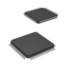
Mounting Type: Surface Mount

Package: 100-LQFP

Quality and Safety Features

Brown-out Detect/Reset and Power-On Reset (POR) for reliable operation under fluctuating power conditions

Watchdog Timer (WDT) to prevent system hang-ups

Compatibility

The device's broad range of connectivity options ensures compatibility with a wide array of existing peripherals and systems.

Application Areas

Suitable for use in low-power and high-performance applications across various fields such as industrial, consumer electronics, medical devices, and automation systems.

Product Lifecycle

Currently, the MSP430F6638IPZR is in an Active phase, with no immediate indication of discontinuation. Texas Instruments typically provides extensive support for product transitions and upgrades.

Several Key Reasons to Choose This Product

Superior low-power consumption for extended battery life

High integration level for simpler, cost-effective designs

Advanced connectivity options provide versatility in application

Comprehensive internal memory facilities support complex algorithms and processes without the need for external components

Solid support and product lifecycle management from Texas Instruments ensure a future-proof solution
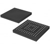
Frequently Asked Questions(FAQ)

How does the MSP430F6638IPZR's 256KB flash memory and 18K×8 RAM configuration support real-time data logging applications, and what are the practical limits for sustained write cycles in such use cases?
The MSP430F6638IPZR provides 256KB of flash memory and 18K×8 bytes (144K bits) of RAM, enabling efficient buffering and storage for real-time data logging. In typical embedded logging scenarios, such as environmental monitoring or sensor acquisition, the flash endurance—often specified at 10,000 cycles per sector—imposes a design constraint rather than a hard limit, assuming wear leveling or sector rotation is implemented. With a 20MHz CPU and DMA-capable peripherals, data can be written to flash in blocks without significant processor overhead. However, continuous byte-by-byte writes would reduce lifespan; thus, application-level buffering into RAM and periodic block writes to flash is recommended. This architecture allows for reliable operation in systems requiring moderate logging throughput over years.
When comparing the MSP430F6638IPZR with other MSP430 family members like the F5xx series, which version offers better peripheral integration for USB-based applications, and why?
The MSP430F6638IPZR supports full-speed USB 2.0 via its integrated USB controller, a feature absent in most MSP430F5xx variants, which typically lack USB hardware. While the F5xx series may offer higher clock speeds or more I/O pins, they do not include native USB transceivers or related logic. For USB-enabled designs—such as firmware flashing, mass storage, or HID devices—the F6638’s built-in USB PHY and associated clock system (including DCO and USB-specific PLL) make it uniquely suited. Thus, when USB connectivity is required, the F6638IPZR provides a more complete solution without external components.
What considerations should be made when selecting the MSP430F6638IPZR for battery-powered industrial sensor nodes operating between -40°C and 85°C?
The MSP430F6638IPZR operates reliably across -40°C to 85°C, meeting industrial temperature requirements. Its low-power modes—down to microamps in standby—are critical for battery longevity. In sleep mode, current draw drops below 1µA, enabling multi-year operation with coin cells or small Li-ion packs. The internal oscillator ensures wake-up timing without external crystals, reducing BOM cost and PCB complexity. Additionally, features like brown-out detection and watchdog timers enhance robustness in noisy environments. Designers must still account for leakage currents at elevated temperatures, but the device’s power management architecture makes it well-suited for energy-constrained deployments.
How does the MSP430F6638IPZR handle simultaneous communication over SPI, UART, and USB, given its finite number of communication peripherals?
The MSP430F6638IPZR includes one UART/USART, two USCI modules supporting SPI, I2C, and UART modes, and a single USB module. These peripherals can operate concurrently using different timing domains: USB runs asynchronously from the main system clock, while SPI and UART share the 20MHz core clock. Through careful scheduling and interrupt prioritization, multiple interfaces can function simultaneously. For example, a USB host could enumerate a device while SPI communicates with an SD card and UART sends debug output. However, shared resources like the DMA channels or CPU bandwidth require allocation planning to avoid bottlenecks in high-throughput scenarios.
Can the MSP430F6638IPZR drive multiple external displays directly, and if so, how does its PWM and DAC capability enable this?
Yes, the MSP430F6638IPZR can drive simple graphical or character-based displays using its dual 12-bit DACs and PWM peripherals. Each DAC outputs analog voltages suitable for driving LCD bias circuits or simple segment drivers. Combined with PWM-controlled backlight dimming, these features allow basic visual feedback without external display controllers. While not capable of handling complex graphics or video, the device can manage small OLEDs, segmented LCDs, or LED indicators with minimal external circuitry. This integration reduces component count in human-machine interface applications where space and power are limited.
What are the implications of using the MSP430F6638IPZR in automotive edge applications where EMI and voltage transients are common?
Although rated for industrial temperatures, the MSP430F6638IPZR is not AEC-Q100 qualified, limiting direct use in stringent automotive systems. However, in non-safety automotive peripherals—such as dashboard sensors or body control modules—it may still be employed with additional protection. Its brown-out detection, reset circuitry, and robust I/O structure help tolerate minor voltage dips. To improve reliability, designers should add TVS diodes on all exposed lines and ensure proper decoupling near Vcc/Vdd pins. Given its low electromagnetic emissions due to controlled switching rates, it remains viable in less demanding automotive subsystems.
How does the 100-LQFP package of the MSP430F6638IPZR affect thermal performance and soldering profile selection?
The 100-pin LQFP (14×14 mm) package offers moderate thermal conductivity through its exposed pad, allowing heat dissipation primarily via convection and conduction to the PCB. While not optimized for high-power applications, it suffices for the MSP430F6638IPZR’s typical power envelope (<200 mW active). During assembly, the device must be handled according to MSL 3 guidelines (168-hour floor life), with reflow profiles adhering to JEDEC J-STD-020. Peak temperatures should not exceed 260°C for more than 10 seconds to preserve internal bonding integrity. Proper land patterns and thermal vias under the package enhance solder joint reliability and prevent popcorning in humid environments.
What role does the internal oscillator play in reducing system cost and board space when using the MSP430F6638IPZR?
The MSP430F6638IPZR features a calibrated internal DCO (Digitally Controlled Oscillator) capable of running up to 20 MHz, eliminating the need for external crystals or resonators in many applications. This reduces component count and simplifies layout, especially in space-constrained designs. Although less accurate than crystal oscillators (±1% typical), it suffices for communication protocols like UART (with baud rate tolerance margins) and SPI/I2C. For USB operation, the device uses a dedicated PLL derived from an external 12-MHz crystal or ceramic resonator, reintroducing one precision component only when needed. Overall, this hybrid approach balances accuracy with cost and size efficiency.
Is it feasible to upgrade firmware in-field on devices using the MSP430F6638IPZR, and what safeguards are necessary during the process?
Yes, the MSP430F6638IPZR supports in-system programming (ISP) and bootloader functionality, enabling firmware updates over USB, UART, or I2C. However, robust error handling is essential to prevent bricking. Critical measures include implementing a dual-bank flash strategy with rollback capability, verifying checksums before writing, and ensuring stable power during erase/write operations. The bootloader should validate firmware signatures if security is a concern. Since flash memory has limited endurance, frequent full-image updates should be avoided unless managed carefully. These practices ensure reliable field upgrades without risking permanent device failure.
How does the MSP430F6638IPZR compare to ARM Cortex-M0+ parts in terms of power efficiency for wireless sensor network applications?
While the MSP430F6638IPZR lacks integrated wireless radios, its ultra-low active and sleep currents (sub-µA in LPM3) outperform most Cortex-M0+ MCUs in idle-dominated workloads. For example, a typical M0+ draws ~10–30 µA/MHz, whereas the F6638IPZR consumes ~50 µA/MHz at 20 MHz but drops below 1 µA in deep sleep. When paired with an external BLE module, the MSP430 can remain in low-power mode while the radio handles communication, yielding longer battery life than M0+ solutions that cannot match such aggressive sleep characteristics. Thus, for duty-cycled sensing with long intervals between transmissions, the F6638IPZR offers superior energy efficiency despite lower computational throughput.
What precautions are necessary when interfacing the MSP430F6638IPZR’s GPIOs to inductive loads or relays?
Driving inductive loads directly from the MSP430F6638IPZR’s 3.3V GPIOs risks damaging pins due to back EMF and overcurrent. Each output must include flyback diodes or use external drivers like MOSFETs or optoisolators. Pull-down resistors (~10 kΩ) prevent floating states during power-up, while series resistors (22–100 Ω) limit transient currents. Additionally, ensure load currents stay within absolute maximum ratings (typically 20 mA per pin, 100 mA total for all I/O). Isolation via relays or solid-state relays further enhances safety in high-voltage environments. These measures protect both the MCU and surrounding circuitry from voltage spikes and electrostatic discharge.
Can the MSP430F6638IPZR be used in medical wearable devices requiring patient data logging and USB connectivity?
The MSP430F6638IPZR is suitable for non-invasive medical peripherals such as pulse oximeters or glucose monitors that log data locally and transfer via USB. Its 16x12-bit ADC provides sufficient resolution for analog biosignal conditioning, while the integrated peripherals reduce external component count. However, certification standards like IEC 60601 apply only to finished systems, not individual ICs. Designers must ensure isolation, noise immunity, and fail-safe behavior meet regulatory expectations. As a RoHS-compliant, REACH-unaffected component, it aligns with environmental directives, but end-product validation remains the responsibility of the integrator.
What impact does the 74 I/O pin count have on PCB routing complexity when using the MSP430F6638IPZR in compact designs?
With 74 general-purpose I/O pins in the 100-LQFP package, the MSP430F6638IPZR enables rich peripheral expansion without requiring multiplexed buses or external expanders. However, dense pinout demands careful PCB layout to avoid crosstalk and signal integrity issues. High-speed signals like USB D+/D− and clock lines should be routed differentially and matched in length. Grouping related functions (e.g., SPI CS lines together) improves trace organization. Using impedance-controlled layers and proper termination helps maintain performance. Despite the pin density, experienced designers can integrate the F6638IPZR effectively into compact form factors by leveraging its flexible pin assignment options in the LQFP package.
How does the MSP430F6638IPZR support secure firmware distribution and execution?
The MSP430F6638IPZR does not include hardware cryptographic engines, but software-based AES or RSA implementations can run on its 16-bit core. Firmware security relies on bootloader integrity, flash write protection bits, and optional checksum verification. Texas Instruments provides tools like TI Secure Microcontroller Development Kit to assist with signing and verification workflows. While not as fast as dedicated crypto cores found in higher-end MCUs, the F6638IPZR’s deterministic execution and small code footprint make it feasible to implement lightweight security protocols for applications requiring authenticity without excessive resource consumption.
What trade-offs exist between using the internal vs. external crystal for USB operation with the MSP430F6638IPZR?
For USB communication, the MSP430F6638IPZR requires a precise 12-MHz reference clock. An external crystal or ceramic resonator provides better frequency stability than internal RC oscillators, ensuring compliance with USB 2.0 timing tolerances (±0.25% max). Using an external crystal increases BOM cost by $0.10–$0.50 but avoids potential enumeration failures caused by timing drift. Internal oscillators alone cannot support USB; thus, external precision sources are mandatory. Designers must also allocate GPIOs for XTAL_IN/XTAL_OUT and include load capacitors (typically 12–22 pF) for oscillation stability. This trade-off favors reliability over cost savings in USB-connected designs.
How does the MSP430F6638IPZR manage power delivery across its 1.8V to 3.6V supply range, and what happens during undervoltage conditions?
The MSP430F6638IPZR dynamically adjusts internal regulators based on the input voltage, maintaining stable core logic and I/O levels. Below 1.8V, the device enters reset state to prevent erratic behavior. Brown-out detection circuitry monitors Vcc and triggers a POR (Power-On Reset) if voltage drops too low, ensuring clean startup or shutdown. During normal operation, dynamic voltage scaling can reduce power by lowering clock frequency or disabling unused peripherals. However, the entire chip must remain within the 1.8–3.6V window; exceeding this range risks latch-up or permanent damage. Decoupling capacitors (100 nF + 10 µF bulk) near Vcc are essential for noise suppression and transient response.
What role does DMA play in offloading the MSP430F6638IPZR’s CPU during data-intensive tasks like ADC sampling or UART transmission?
The MSP430F6638IPZR includes DMA channels that allow peripherals to access memory directly without CPU intervention. For instance, the 16-channel ADC can stream samples to RAM automatically, freeing the CPU for processing or entering low-power modes. Similarly, UART transmit/receive buffers can be managed by DMA, minimizing interrupt overhead. This capability is crucial in real-time systems where predictable latency matters. Without DMA, continuous ADC conversion would consume significant CPU cycles, increasing power usage and complicating timing-critical loops. By leveraging DMA, the F6638IPZR achieves efficient data movement while preserving responsiveness and energy efficiency.

Parts with Similar Specifications

The three parts on the right have similar specifications to Texas Instruments MSP430F6638IPZR

Product Attribute MSP430F6638IPZ MSP430F6658IPZR MSP430F6637IPZR MSP430F6636IPZR
Part Number MSP430F6638IPZ MSP430F6658IPZR MSP430F6637IPZR MSP430F6636IPZR
Manufacturer Texas Instruments Texas Instruments Texas Instruments Texas Instruments
Core Size - - - -
Package / Case - 196-LFBGA 16-DIP (0.300', 7.62mm) 64-VFQFN Exposed Pad
Operating Temperature - -40°C ~ 85°C 0°C ~ 70°C -40°C ~ 85°C
Mounting Type - Surface Mount Through Hole Surface Mount
Base Product Number - DAC34H84 MAX500 ADS62P42
Program Memory Size - - - -
Series - - - -
EEPROM Size - - - -
Core Processor - - - -
Oscillator Type - - - -
Package - Tape & Reel (TR) Tube Tape & Reel (TR)
Program Memory Type - - - -
Connectivity - - - -
Peripherals - - - -
RAM Size - - - -
Supplier Device Package - 196-NFBGA (12x12) 16-PDIP 64-VQFN (9x9)
Number of I/O - - - -
Speed - - - -
Data Converters - - - -
Voltage - Supply (Vcc/Vdd) - - - -

MSP430F6638IPZR Datasheet PDF

Download MSP430F6638IPZR pdf datasheets and Texas Instruments documentation for MSP430F6638IPZR - Texas Instruments.

PCN Design/Specification
CC430Fxx/MSP430F5xx/MSP430F6xx/MSP430Vxx 29/Jan/20.pdf MSP430F54yy/F6yy Datasheet Update 26/Aug/2013.pdf
HTML Datasheet
MSP430F663x Datasheet.pdf
PCN Assembly/Origin
2.73KHz.pdf
PCN Other
2.73KHz.pdf

Customer Reviews

Evaluation: 10 Articles

  • Emil***rperTech
    Jun 23, 2026

    Works exactly as described. I used it as a USB-to-SPI bridge in a small MCU development project and communication was stable from the first setup.

  • Liam***terTech
    Jun 15, 2026

    Used this CPLD in a logic control project. Programming was straightforward and signal timing matched the design requirements.

  • Nath***rooks
    Jun 11, 2026

    Installed this power component in a converter board. Output remained stable under different load conditions and thermal performance was better than expected.

  • Dani***alkerTech
    Jun 1, 2026

    Product works, but setup took more effort than expected. Once configured the MCU ran reliably, although documentation support felt older compared with newer platforms. Fine for maintenance projects.

  • Yuki***aka88
    May 26, 2026

    信号通信プロジェクトでこのRS-485トランシーバーを使用しました。設置は簡単で、長距離ケーブルでも通信は安定していました。消費電力も、以前使用していたものより低くなっています。

  • Stev***aker
    May 20, 2026

    Solid diode for power rectification. Works well in switching circuits.

  • Bran***Lewis
    May 11, 2026

    Compact FPGA with good performance. Suitable for basic signal processing tasks.

  • Oliv***arris
    May 7, 2026

    Reliable I/O expander. Works well in embedded control applications.

  • Jess***Jones
    Apr 17, 2026

    It offers good value for the price, and the specifications match the description. I’ve been using it for two days with no issues, and I’ll definitely buy it again if I need it in the future.

  • Mich***Smith
    Apr 17, 2026

    Shipping was on time, the component pins are neatly aligned, and I tested 10 of them with a multimeter—all readings were within the specified range. Highly recommended.

Write a Review

Your Email address will not be published.

Shipment

Delivery Time

In-stock items can be shipped within 24 hours. Some parts will be arranged for delivery within 1-2 days from the date all items arrive at our warehouse. And Allelco ships order once a day at about 17:00, except Sunday. Once the goods are shipped, the estimated delivery time depends on the shipping methods and Delivery destination. The table below shows are the logistic time for some common countries.

Delivery Cost

  1. Use your express account for shipment if you have one.
  2. Use our account for the shipment. Refer to the table below for the approximate charges.
(Different time frame / countries / package size has different price.)

Delivery Method

  1. Global Common Shipment by DHL / UPS / FedEx / TNT / EMS / SF we support.
  2. Others more shipping ways, please get in touch with your customer manager.

Common Countries Logistic Time Reference
Region Country Logistic Time(Day)
America United States 5
Brazil 7
Europe Germany 5
United Kingdom 4
Italy 5
Oceania Australia 6
New Zealand 5
Asia India 4
Japan 4
Middle East Israel 6
DHL & FedEx Shipment Charges Reference
Shipment charges(KG) Reference DHL(USD$)
0.00kg-1.00kg USD$30.00 - USD$60.00
1.00kg-2.00kg USD$40.00 - USD$80.00
2.00kg-3.00kg USD$50.00 - USD$100.00
Note:
The above table is for reference only. There may have some data bias for the uncontrollable factors.
Contact us if you have any questions.
  • QC (Quality Warranty)
  • Payment Support
  • Packaging
  • Certifications & Memberships

QC (Quality Warranty)

Allelco is committed to exceeding customer expectations through customer service excellence, order accuracy, and on-time delivery.
This is achieved through our commitment to the continual improvement of our processes, services, and products.


Strict quality inspection builds a solid foundation for electronic component quality.
  1. Visual inspection
  2. Performance testing and reliability verification
  3. Standardized full-process testing
  4. Precise control of every parameter
We eliminate defective components and ensure the stable operation of electronic devices through professional quality standards.

Payment Support

The payment method can be chosen from the methods shown below: Wire Transfer (T/T, Bank Transfer), Western Union, Credit card, PayPal.
  • HKBea
  • Paypal
  • MasterCard
  • Western-Union
  • VISA
Stable Delivery, Sincere Partnership — Your Faithful Supply Chain Partner
  • Efficient Supply Management
  • Cost-Saving Procurement
  • Fast Sourcing & Delivery
Contact us if you have any questions.

Packaging

Electrostatic Discharge Protection and Handling

All electrostatic-sensitive components are handled in accordance with electrostatic discharge control procedures. The products are hermetically sealed in anti-static safe packaging to prevent electrostatic damage. Appropriate labeling is also applied for identification and traceability. This ensures product integrity during storage, handling and transportation.


ESD

Certifications & Memberships

Third-party certified, strict quality control. Our certification
  • ISO 9001: 2015
  • ISO 13485: 2016
  • ISO 14001: 2015
  • ISO 28000: 2007
  • ISO 45001: 2018
  • GB/T 27922-2011
  • SMTA
  • IPC
  • ESD
  • PSMA
MSP430F6638IPZR Image

MSP430F6638IPZR

Texas Instruments
32D-MSP430F6638IPZR

Want a better price? Add to Cart and Submit RFQ now, we'll contact you immediately.

0 RFQ
Shopping cart (0 Items)
It is empty.
Compare List (0 Items)
It is empty.
Feedback

Your feedback matters! At Allelco, we value the user experience and strive to improve it constantly.
Please share your comments with us via our feedback form, and we'll respond promptly.
Thank you for choosing Allelco.

Subject
E-mail
Comments
Captcha
Drag or click to upload file
Upload File
types: .xls, .xlsx, .doc, .docx, .jpg, .png and .pdf.
Max file size: 10MB