
TAS5766MDCAR (1)
Manufacturer Part Number
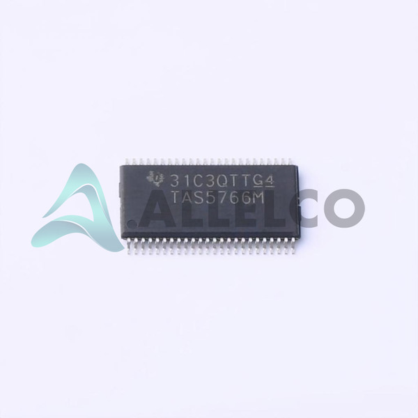
TAS5766MDCAR
Manufacturer
Texas Instruments
Introduction
Integrated Circuit (IC) for audio applications
Part of the PurePath series
Product Features and Performance
2-Channel (Stereo) Class D amplifier
Suitable for a wide range of operating temperatures (-40°C to 125°C)
Provides short-circuit protection and Depop functionality
Operates on a supply voltage of 3V to 3.6V
Product Advantages
Efficient Class D amplification technology
Wide temperature range for versatile applications
Built-in protection features for reliable operation
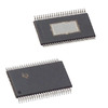
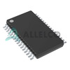
Compact 48-HTSSOP package
TAS5766MDCAR (2)
Key Technical Parameters
Package: 48-HTSSOP
Mounting Type: Surface Mount
Output Type: 2-Channel (Stereo)
Voltage Supply: 3V to 3.6V
Quality and Safety Features
RoHS3 compliant
Short-circuit protection
Compatibility
Compatible with a variety of audio applications and systems
Application Areas
Audio amplification in consumer electronics, automotive systems, and other applications requiring compact and efficient Class D amplifiers
Product Lifecycle
Currently available, not nearing discontinuation
Replacements and upgrades may be available in the future
Key Reasons to Choose This Product
Efficient and energy-saving Class D amplification
Wide operating temperature range for versatile use
Built-in protection features for reliable performance
Compact and space-saving 48-HTSSOP package
Compliance with RoHS3 regulations for environmental responsibility
 TAS5766MRMTRTexas InstrumentsIC AMP CLASS D STEREO 48VQFN
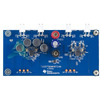 TAS5766MRMTEVMTexas InstrumentsEVAL MODULE FOR TAS5766
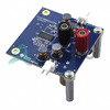 TAS5766MDCAEVMTexas InstrumentsEVAL MODULE FOR TAS5766
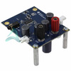 TAS5760XXEVMTexas InstrumentsEVAL MODULE FOR TAS5760XX
 TAS5762LYFFTTexas InstrumentsPROTOTYPE


